Publication 1763-RM001C-EN-P - October 2009
244 Sequencer Instructions
If the position is equal to zero at start-up, when you switch the controller
from the program mode to the run mode, the instruction operation
depends on whether the rung is true or false on the first scan.
• If the rung is true, the instruction transfers the value in step zero.
• If the rung is false, the instruction waits for the first rung transition
from false-to-true and transfers the value in step one.
The bits mask data when reset (0) and pass data when set (1). The
instruction will not change the value in the destination word unless you
set mask bits.
The mask can be fixed or variable. It is fixed if you enter a hexadecimal
code. It is variable if you enter an element address or a file address (direct
or indirect) for changing the mask with each step.
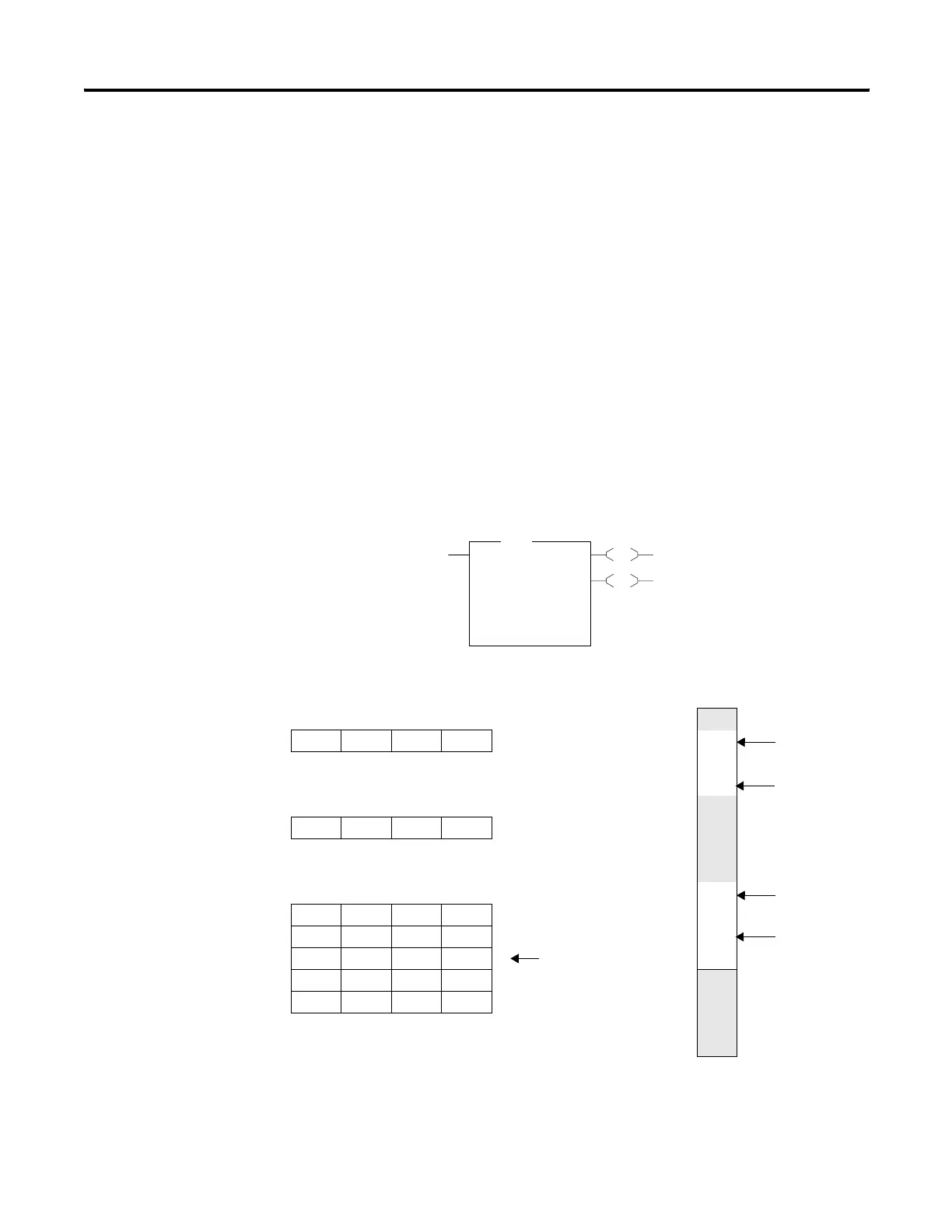
The following figure indicates how the SQO instruction works.
Destination O:14.0 External Outputs (O:14)
at Step 2
15 8 7 0
00
0000 0101 0000 1010 01 ON
02
Mask Value 0F0F 03 ON
15 8 7 0
04
0000 1111 0000 1111
05
06
Sequencer Output File #B10:1
07
Word Step 08 ON
B10:1 0000 0000 0000 0000 0 09
B10:2 1010 0010 1111 0101 1 10 ON
B10:3 1111 0101 0100 1010 2 Current Step 11
B10:4 0101 0101 0101 0101 3
12
B10:5 0000 1111 0000 1111 4
13
14
15
EN
DN
SQO
Sequencer Output
File #B10:1
Mask 0F0F
Dest O14:0
Control R6:20
Length 4<
Position 2<
SQO
efesotomasyon.com - Allen Bradley,Rockwell,plc,servo,drive

 Loading...


