Publication 1763-RM001C-EN-P - October 2009
I/O Configuration 27
Input Channel Filtering
The analog input channels incorporate on-board signal conditioning, to
distinguish AC power line noise from normal variations in the input
signal. Frequency components of the input signal at the filter frequency
are rejected. Frequency components below the filter bandwidth (-3 dB
frequency) are passed with under 3 dB of attenuation. This pass band
allows the normal variation of sensor inputs such as temperature, pressure
and flow transducers to be input data to the processor. Noise signals
coupled in at frequencies above the pass band are sharply rejected. An
area of particular concern is the 50/60 Hz region, where pick-up from
power lines can occur.
Converting Analog Data
The analog input circuits are able to monitor voltage signals and convert
them to digital data. There are three terminals assigned to the input
channels that provide two voltage inputs, and a return signal (commons).
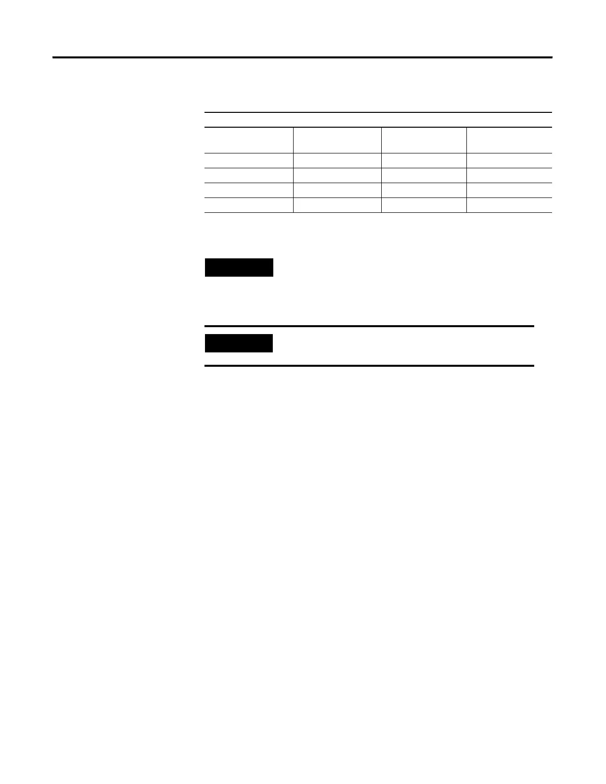
Programmable Filter Characteristics
1st Notch Freq (Hz) Filter Bandwidth (-3
dB Freq Hz)
Settling Time
(mSec)
Resolution (Bits)
10 2.62 100.00 10
50 13.10 20.00 10
60 15.72 16.67 10
250 65.50 4 10
TIP
•10 Hz is the default setting
•The total update time is one ladder scan time plus the settling time.
EXAMPLE
If a 250 Hz filter is selected, the maximum update
Time = ladder scan time + 4ms
efesotomasyon.com - Allen Bradley,Rockwell,plc,servo,drive

 Loading...


