Publication 1763-RM001C-EN-P - October 2009
Process Control Instruction 301
Scaling to Engineering Units
Scaling lets you enter the setpoint and zero-crossing deadband values in
engineering units, and display the process variable and error values in the
same engineering units. Remember, the process variable PV must still be
within the range 0 to 16383. The PV is displayed in engineering units,
however.
Select scaling as follows:
1. Enter the maximum and minimum scaling values MaxS and MinS in
the PID control block. The MinS value corresponds to an analog
value of zero for the lowest reading of the process variable. MaxS
corresponds to an analog value of 16383 for the highest reading.
These values reflect the process limits. Setpoint scaling is selected
by entering a non-zero value for one or both parameters. If you
enter the same value for both parameters, setpoint scaling is
disabled.
For example, if measuring a full scale temperature range of -73°C
(PV=0) to +1156°C (PV=16383), enter a value of -73 for MinS and
1156 for MaxS. Remember that inputs to the PID instruction must be
0 to 16383. Signal conversions could be as follows:
2. Enter the setpoint (word 2) and deadband (word 9) in the same
scaled engineering units. Read the scaled process variable and
scaled error in these units as well. The control output percentage
(word 16) is displayed as a percentage of the 0 to 16383 CV range.
The actual value transferred to the CV output is always between 0
and 16383.
When you select scaling, the instruction scales the setpoint, deadband,
process variable, and error. You must consider the effect on all these
variables when you change scaling.
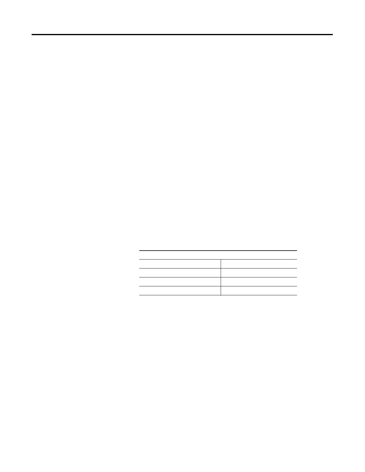
Example Values
Process limits -73 to +1156°C
Transmitter output (if used) +4 to +20 mA
Output of analog input module 0 to 16383
PID instruction, MinS to MaxS -73 to +1156°C
efesotomasyon.com - Allen Bradley,Rockwell,plc,servo,drive

 Loading...


