Publication 1763-RM001C-EN-P - October 2009
I/O Configuration 31
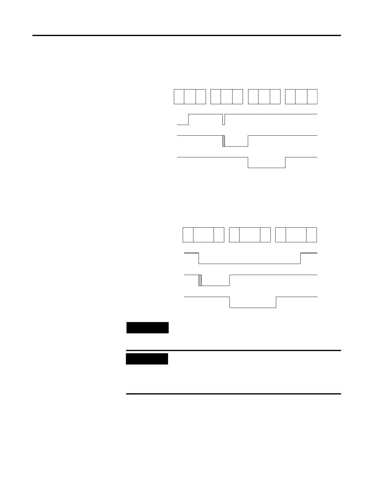
Falling Edge Behavior - Example 1
Falling Edge Behavior - Example 2
TIP
The “gray” area of the Latched Status waveform is the
input filter delay.
IMPORTANT
The input file value does not represent the external input
when the input is configured for latching behavior.
When configured for falling edge behavior, the input file
value is normally “on” (“off” for 1 scan when a falling
edge pulse is detected).
Scan Number (X) Scan Number (X+1) Scan Number (X+2)
External
Input
Latched
Status
Input File
Value
Input
Scan
Ladder
Scan
Output
Scan
Scan Number (X+3)
Input
Scan
Ladder
Scan
Output
Scan
Input
Scan
Ladder
Scan
Output
Scan
Input
Scan
Ladder
Scan
Output
Scan
Scan Number (X) Scan Number (X+1) Scan Number (X+2)
External
Input
Latched
Status
Input File
Value
Input
Scan
Ladder
Scan
Output
Scan
Input
Scan
Ladder
Scan
Output
Scan
Input
Scan
Ladder
Scan
Output
Scan
efesotomasyon.com - Allen Bradley,Rockwell,plc,servo,drive

 Loading...


