Publication 1763-RM001C-EN-P - October 2009
ASCII Instructions 321
– Characters Sent (.POS) can be greater than the String Length
(.LEN) if inserted values from in-line indirection are used. If the
String Length (.LEN) is greater than 82, the string written to the
destination is truncated to 82 characters.
• Error displays the hexadecimal error code that indicates why the ER
bit was set in the control data file. See page 337 for error code
descriptions.
Addressing Modes and File Types can be used as shown below:
Example
In this example, when the rung goes from false-to-true, the control
element Enable (EN) bit is set. When the instruction is placed in the ASCII
queue, the Queue bit (EU) is set. The Running bit (RN) is set when the
instruction is executing. The DN bit is set on completion of the
instruction.
Forty characters from string ST37:40 are sent through channel 0. The Done
bit (DN) is set and a value of 40 is present in the POS word of the ASCII
control data file.
When an error is detected, the error code is written to the Error Code Byte
and the Error Bit (ER) is set. See ASCII Instruction Error Codes on page
337 for a list of the error codes and recommended action to take.
AWT Instruction Valid Addressing Modes and File Types
For definitions of the terms used in this table see Using the Instruction Descriptions on page 82.
Parameter
Data Files
(1)
Function Files
CS - Comms
IOS - I/O
DLS - Data Log
Address
Mode
Address Level
O
I
S
B
T, C, R
N
F
ST
L
MG, PD
RI/RIX
PLS
RTC
HSC
PTO, PWM
STI
EII
BHI
MMI
LCD
Immediate
Direct
Indirect
Bit
Word
Long Word
Element
Channel • •
Source •
• •
Control •
• •
(1) The Control data file is the only valid file type for the Control Element.
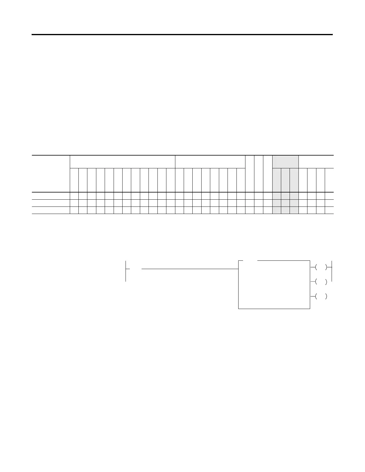
AWT
ASCII WRITE
Channel
Source
I:1
10
[
[
Control
0
ST37:20
R6:23
String Length
Characters Sent
40
0
0
EN
DN
ER
Error
If input slot 1, bit 10 is set, write 40 characters from
ST37:20 to the display device.
efesotomasyon.com - Allen Bradley,Rockwell,plc,servo,drive

 Loading...


