Publication 1763-RM001C-EN-P - October 2009
ASCII Instructions 329
• OR Mask is the mask used to set the RTS control line. Bit 1
corresponds to the RTS control line. A value of “2” in the OR mask
sets the RTS control line; a value of “0” leaves the line unchanged.
• Control is the control data file. See page 313.
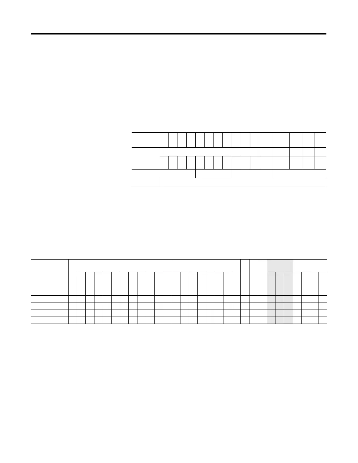
• Channel Status displays the current status (0000 to 001F) of the
handshake lines for the specified channel. This status is read-only
and resides in the .POS field in the control data file. The following
shows how to determine the channel status value. In this example,
the value is 001F.
• Error displays the hexadecimal error code that indicates why the ER
bit was set in the control data file. See page 337 for error code
descriptions.
Addressing Modes and File Types can be used as shown below:
Instruction Operation
This instruction executes on either a false or true rung. However a
false-to-true rung transition is required to set the EN bit to repeat the
instruction.
Channel
Status Bit
15 14 13 12 11 10 9 8 7 6 5 4 3 2 1 0
Handshake
Control Line
Setting
reserved -- -- RTS CTS
000000000001 1 1 1 1
Channel
Status
001 F
Word 2 of the Control Element = 001F
AHL Instruction Valid Addressing Modes and File Types
For definitions of the terms used in this table see Using the Instruction Descriptions on page 82.
Parameter
Data Files
(1)
Function Files
CS - Comms
IOS - I/O
DLS - Data Log
Address
Mode
Address Level
O
I
S
B
T, C, R
N
F
ST
L
MG, PD
RI/RIX
PLS
RTC
HSC
PTO, PWM
STI
EII
BHI
MMI
LCD
Immediate
Direct
Indirect
Bit
Word
Long Word
Element
Channel • •
AND Mask •• ••• •
• • •
OR Mask •• ••• •
• • •
Control •
• •
(1) The Control data file is the only valid file type for the Control Element.
efesotomasyon.com - Allen Bradley,Rockwell,plc,servo,drive

 Loading...


