Publication 1763-RM001B-EN-P - April 2007
Communications Instructions 367
Data Table Address
This variable defines the starting address in the local controller. Valid file
types for the Data Table Address are shown below:
Size in Elements
This variable defines the amount of data (in elements) to exchange with
the target device.
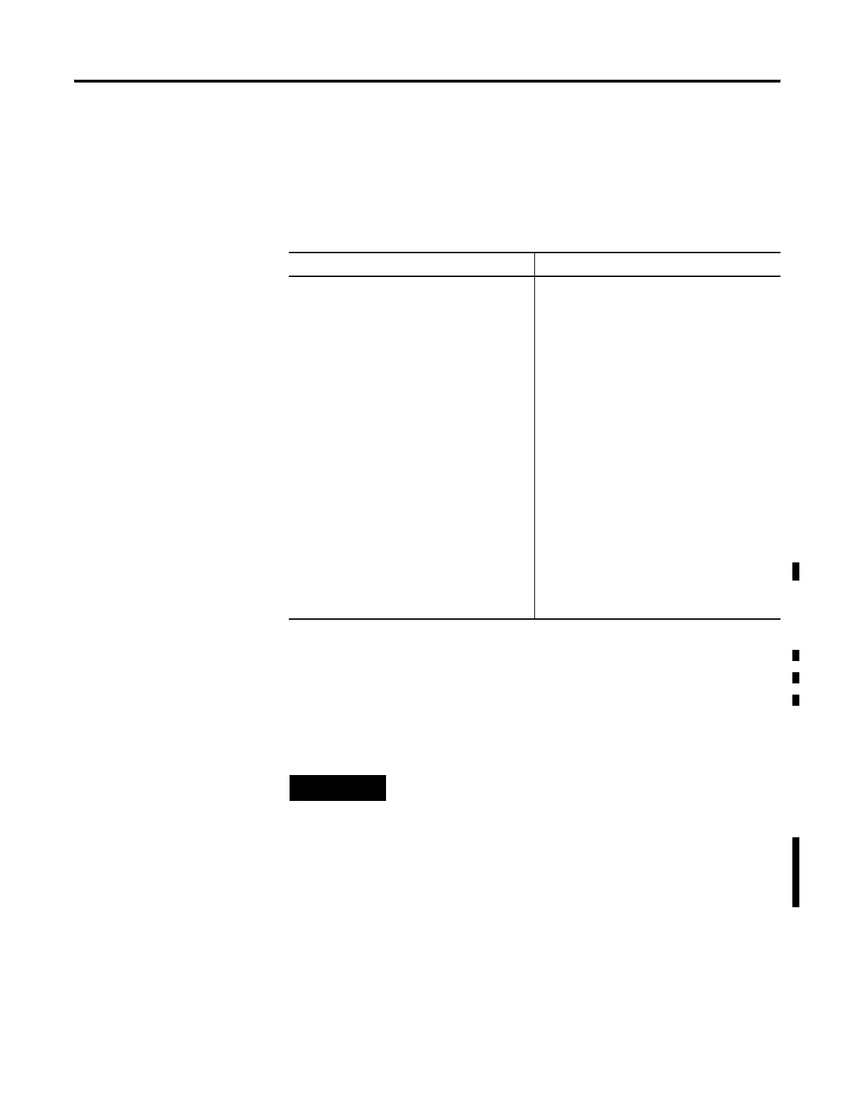
Message Read Message Write
Bit (B)
Timer (T)
Counter (C)
Control (R)
Integer (N)
Floating Point (F)
(1)
Long Word (L)
String (ST)
(3)
(1) Message Type must be 500CPU or PLC5. The Local File Type and Target File Type must both be Floating Point.
Output (O)
Input (I)
Bit (B)
Timer (T)
Counter (C)
Control (R)
Integer (N)
Floating Point (F)
(1)
Long Word (L)
String (ST)
(2)
(3)
Real-Time Clock (RTC)
(4)
(2) 485CIF write-to-485CIF only for MicroLogix 1100 OS Series A FRN 3 or earlier.
(3) MicroLogix 1100 OS Series B FRN 4 or later.
(4) 500CPU write RTC-to-Integer or RTC-to-RTC only.
TIP
Only Bit (B) and Integer (N) file types are valid for
Modbus Command messages. Modbus bit commands
require a starting bit address for the Data Table Address.
Floating Point (F) and Long (L) file types are valid for
Modbus Command messages for Holding Registers
(commands 03, 06 and 16) when Data is configured for
32 bit.
efesotomasyon.com - Allen Bradley,Rockwell,plc,servo,drive

 Loading...


