Publication 1763-RM001B-EN-P - April 2007
370 Communications Instructions
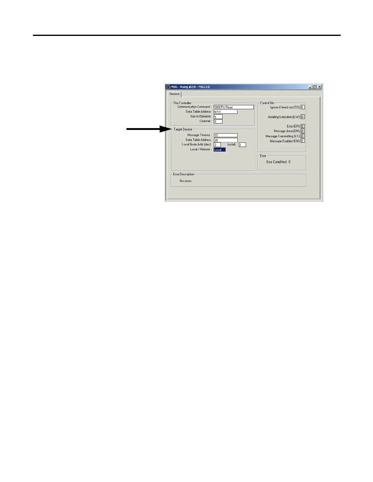
“Target Device” Parameters
Message Timeout
This value defines how long, in seconds, the message instruction has to
complete its operation once it has started. Timing begins when the
false-to-true rung transition occurs, enabling the message. If the timeout
period expires, the message errors out. The default value is 5 seconds (2
seconds for Modbus commands). The maximum timeout value is 255
seconds.
Message Timeout for any MicroLogix 1100 channel 1 MSG can not be
modified in the Ethernet Message Setup dialog box. It is assigned by the
processor and is determined by adding the Channel 1 MSG Connection
Timeout to the MSG Reply Timeout, then adding 15 seconds. This value
can be modified by changing one or both of the timeout values in the
channel configuration screen for channel 1. The modified message
timeout applies to all Ethernet MSG instructions.
MSG timeout for channel 1 = MSG Connection Timeout + MSG
Reply Timeout + 15 (seconds)
If the message timeout is set to zero, the message instruction will never
timeout. Set the Time Out bit (TO = 1) to flush a message instruction from
its buffer if the destination device does not respond to the
communications request.
efesotomasyon.com - Allen Bradley,Rockwell,plc,servo,drive

 Loading...


