EasyManuals Logo

Allen-Bradley MicroLogix 1100 Instruction Set Reference Manual

Allen-Bradley MicroLogix 1100
616 pages
To Next Page IconTo Next Page
To Previous Page IconTo Previous Page
Page #397 background imageLoading...
Page #397 background image
Publication 1763-RM001B-EN-P - April 2007
Communications Instructions 397
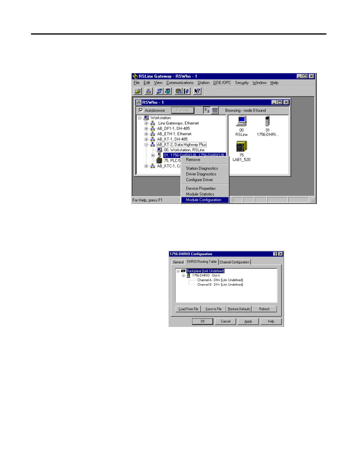
Right Click your mouse on top of the DHRIO module and a drop down
box will open.
Select Module Configuration by clicking with the left mouse button.
Select DHRIO Routing Table tab. If no routing table has been created the
following should appear.
Right click on the Backplane and left click on Edit Module. Make sure that
the Back plane Link ID is set to 20.
Right click on the 1756-DHRIO module and left click on Edit Module.
Make sure that CH A's Link ID is set for 7 and CH B's Link ID is set for 2.
Select OK. Channel B is actually not necessary.
Right click on the Backplane and left click on Add Module. Left click on
1756-ENET.
Enter the correct slot number 2 and Link ID 16 for the ENET module.
efesotomasyon.com - Allen Bradley,Rockwell,plc,servo,drive

Table of Contents

Other manuals for Allen-Bradley MicroLogix 1100

Questions and Answers:

Question and Answer IconNeed help?

Do you have a question about the Allen-Bradley MicroLogix 1100 and is the answer not in the manual?

Allen-Bradley MicroLogix 1100 Specifications

General IconGeneral
Processor32-bit
Programming SoftwareRSLogix 500
MountingDIN rail or panel mount
Power Supply24V DC
TypeCompact PLC
Digital Inputs12
Digital Outputs8
Analog Inputs4 (depending on model)
Analog OutputsOptional with expansion module
Programming LanguageLadder Logic
Operating Temperature0 to 55 °C (32 to 131 °F)
SeriesMicroLogix

Related product manuals