Publication 1763-RM001C-EN-P - October 2009
LCD - LCD Information 449
program. By setting this bit to ON (1), you can let your controller display
LCD instructions or get keypad inputs from the user at power-up, without
additional operations.
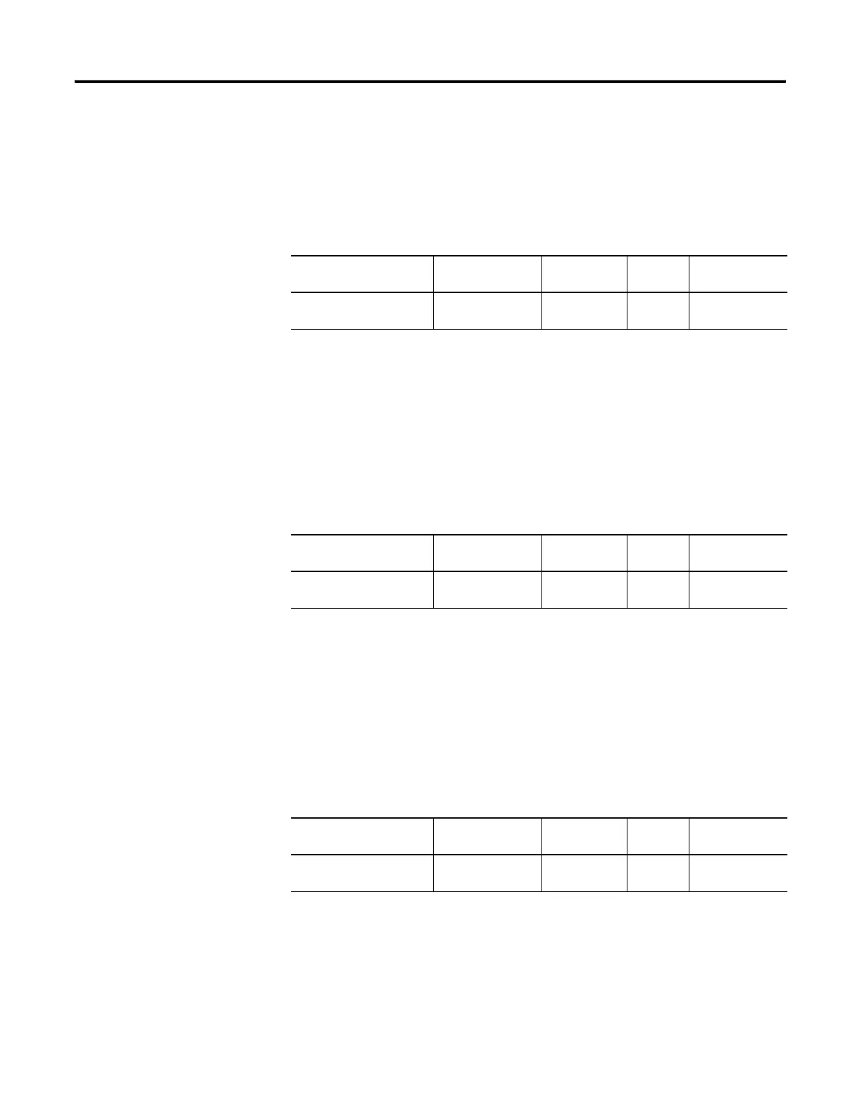
Data Input Timeout of LCD instruction (TO)
Data Input Timeout of LCD instruction (TO) specifies timeout period for
data input when key inputs are obtained from the user using the LCD
instruction in the ladder program. When this word is set to zero (0), it
means no timeout is used. When set to a positive value, the LCD exits
U-MSG mode and continues to the upper menu if there is no keypad
input for more than the specified timeout period (in seconds).
LCD Instruction Job Done (DN)
LCD Instruction Job Done (DN) is set (1) when an LCD instruction is
completed. If the Display With Input bit of the LCD instruction is clear (0,
No), DN bit is set (1) immediately after its execution result is displayed on
the LCD. If the Display With Input bit is set (0, Yes), DN bit is set (1)
when the OK or ESC key is pressed.
LCD Display Operation Error Bit (ERR)
LCD Display Operation Error Bit (ERR) bit indicates whether there is a
Trimpot range error at each program download. Whenever a program is
downloaded, the controller compares the old Trimpot values (POT0 and
POT1) with the new Trimpot range (TMIN to TMAX) and sets (1) ERR bit
if an error is found and resets (0) if no error is found.
Feature Address Data Format Type User Program
Access
TO - Data Input Timeout of
LCD instruction
LCD:0.TO word (INT) control read-only
Feature Address Data Format Type User Program
Access
DN - LCD Instruction Job
Done
LCD:0/DN binary (bit) status read-only
LCD Function File
Feature Address Data Format Type User Program
Access
ERR - LCD Display
Operation Error Bit
LCD:0/ERR binary (bit) status read-only
efesotomasyon.com - Allen Bradley,Rockwell,plc,servo,drive

 Loading...


