Publication 1763-RM001C-EN-P - October 2009
Protocol Configuration 515
Monitor Active Stations
To see which slave stations are active when the channel is configured for
Standard Polling Mode (either single or multiple message per scan), view
the DF1 Half-Duplex Master Active Node Table. The table is stored in the
Communications Status Function File, words CSx:27 to CSx:42, where x is
the channel number (x = 0 for MicroLogix 1100). Each bit in the table
represents a station on the link, from 0 to 254, starting with CSx:27/0 for
address 0 and CSx:42/14 for address 254. The bit for address 255 (CSx:42/
15) is never set, since it is the broadcast address, which never gets polled.
When valid Normal and/or Priority Poll Ranges are defined:
• if a slave responded the last time it was polled by the master, the bit
corresponding to its address is set (1 = active).
• if a slave didn’t respond the last time it was polled by the master,
the bit corresponding to its address is cleared (0 = inactive).
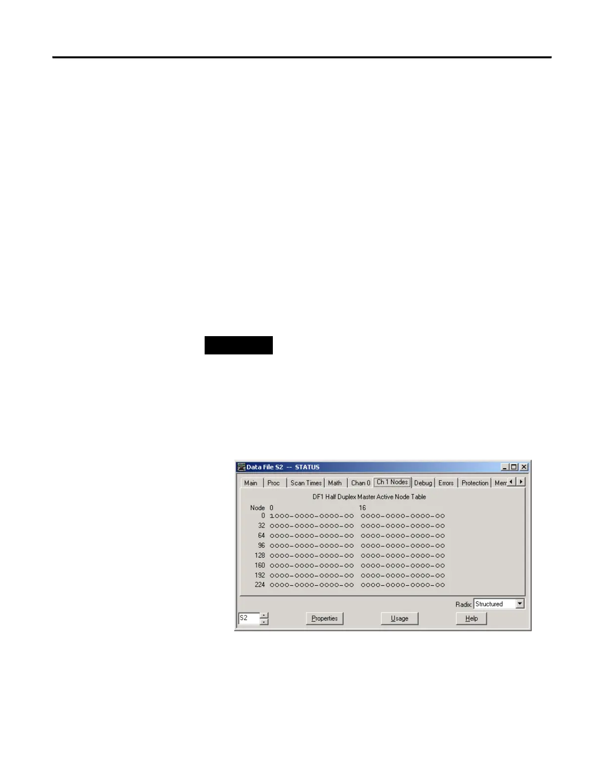
If you are using RSLogix 500 version 7.00.00 or higher, you can view the
active node table by clicking on “Processor Status” and then selecting the
tab for the DF1 Master channel.
Example Active Node Table
At power-up or after reconfiguration, the master station assumes that all
slave stations are inactive. A station is shown active only after it responds
to a poll packet.
NOTE
The bit corresponding to the address configured for the
DF1 Master is always cleared because the master address
never gets polled.
efesotomasyon.com - Allen Bradley,Rockwell,plc,servo,drive

 Loading...


