Publication 1763-RM001C-EN-P - October 2009
Knowledgebase Quick Starts 549
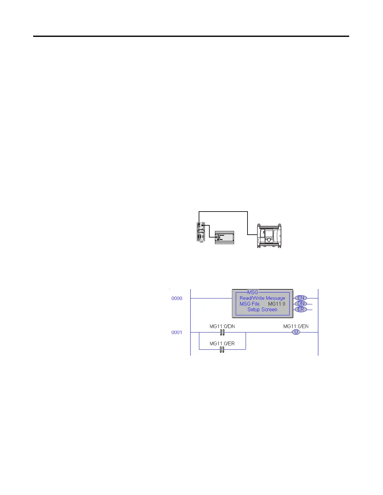
Continuous Message Example:
The following example illustrates how, by using the MSG Done (DN) and
Error (ER) bits to unlatch the Enable (EN) bit the MSG instruction can be
configured for continuous execution.
This example uses MG11:0 for the MSG file and will require two
MicroLogix controllers one a ML1100 and the other either a ML1000 or
ML1100. The ML1100 will need to be configured as Node 1 and the other
processor as node 4.
The processor at node 1 will contain the ladder logic below and transfer
data from it's N7:0 Integer file to the processor at node 4's N7:0 Integer
file. Since N7:0 is the source file for this example, data must be entered
into this register for node 1. For this example Locate N7:0 in the ML1500
(Node 1) and enter the value 63.
MicroLogix 1100 (Node 1) Ladder Logic
TERM
A
B
COM
SHLD
CHS GND
TX
TX PWR
TX
DC SOURCE
CABLE
EXTERNAL
MicroLogix 1100
Node 1
M
i
c
r
o
L
o
g
i
x
1
0
0
0
N
o
d
e
4
efesotomasyon.com - Allen Bradley,Rockwell,plc,servo,drive

 Loading...


