EasyManuals Logo

Allen-Bradley MicroLogix 1100 Instruction Set Reference Manual

Allen-Bradley MicroLogix 1100
616 pages
To Next Page IconTo Next Page
To Previous Page IconTo Previous Page
Page #66 background imageLoading...
Page #66 background image
Publication 1763-RM001C-EN-P - October 2009
66 Function Files
66 - Function Code 6 Message Counter
67 - Function Code 8 Message Counter
68 - Function Code 15 Message Counter
69 - Function Code 16 Message Counter
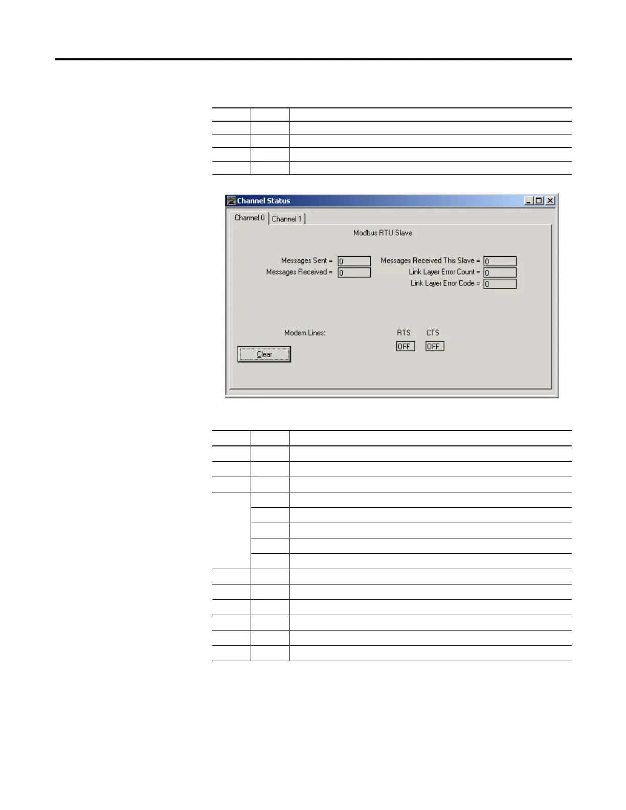
Modbus RTU Master Diagnostic Counters Block (Data Link Layer)
Word Bit Description
6 - Diagnostic Counters Category Identifier Code (always 2)
7 - Length (always 30)
8 - Format Code (always 9)
9 0 CTS
1RTS
2 Reserved
3 Reserved
4 to 15 Reserved
10 - Total Message Packets Sent
11 - Reserved
12 - Total Message Packets Received
13 - Link Layer Error Count
14 - Link Layer Error Code
15 to 22 - Reserved
Modbus RTU Slave Diagnostic Counters Block (Presentation Layer)
Word Bit Description
efesotomasyon.com - Allen Bradley,Rockwell,plc,servo,drive

Table of Contents

Other manuals for Allen-Bradley MicroLogix 1100

Questions and Answers:

Question and Answer IconNeed help?

Do you have a question about the Allen-Bradley MicroLogix 1100 and is the answer not in the manual?

Allen-Bradley MicroLogix 1100 Specifications

General IconGeneral
Processor32-bit
Programming SoftwareRSLogix 500
MountingDIN rail or panel mount
Power Supply24V DC
TypeCompact PLC
Digital Inputs12
Digital Outputs8
Analog Inputs4 (depending on model)
Analog OutputsOptional with expansion module
Programming LanguageLadder Logic
Operating Temperature0 to 55 °C (32 to 131 °F)
SeriesMicroLogix

Related product manuals