Publication 1763-RM001C-EN-P - October 2009
96 Using the High-Speed Counter and Programmable Limit Switch
Counting Enabled (CE)
The CE (Counting Enabled) control bit is used to enable or disable the
High-Speed Counter. When set (1), counting is enabled, when clear (0,
default) counting is disabled. If this bit is disabled while the counter is
running, the accumulated value is held; if the bit is then set, counting
resumes.
This bit can be controlled by the user program and retains its value
through a power cycle. This bit must be set for the high-speed counter to
operate.
Set Parameters (SP)
The SP (Set Parameters) control bit is used to load new variables to the
HSC sub-system. When an OTE instruction with the address of HSC:0/SP
is solved true (off-to-on rung transition), all configuration variables
currently stored in the HSC function are checked and loaded into the HSC
sub-system. The HSC sub-system then operates based on those newly
loaded settings.
This bit is controlled by the user program and retains its value through a
power cycle. It is up to the user program to set and clear this bit. SP can
be toggled while the HSC is running and no counts are lost.
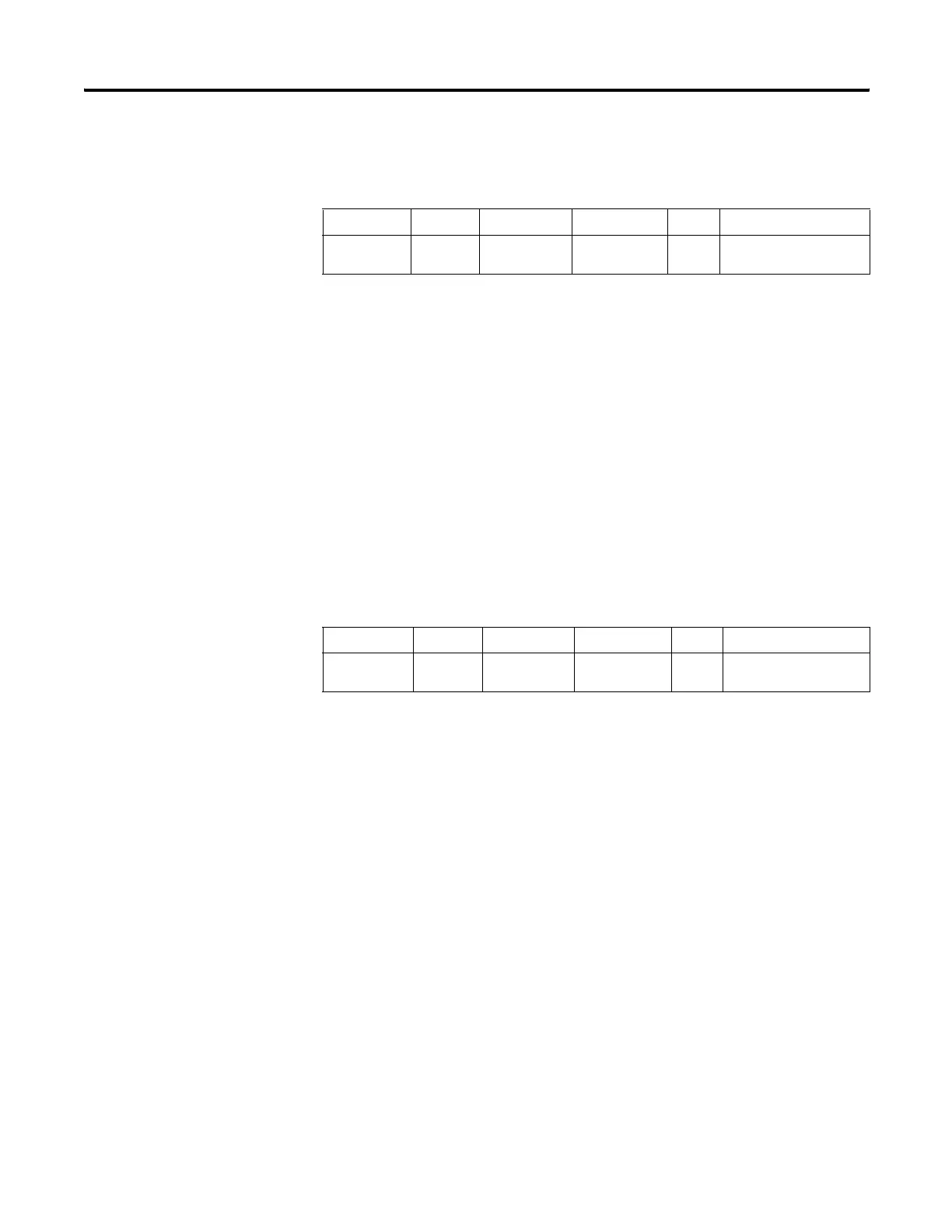
Description Address Data Format
HSC Modes
(1)
(1) For Mode descriptions, see HSC Mode (MOD) on page 107.
Type User Program Access
CE - Counting
Enabled
HSC:0/CE bit 0 to 7 control read/write
Description Address Data Format
HSC Modes
(1)
(1) For Mode descriptions, see HSC Mode (MOD) on page 107.
Type User Program Access
SP - Set
Parameters
HSC:0/SP bit 0 to 7 control read/write
efesotomasyon.com - Allen Bradley,Rockwell,plc,servo,drive

 Loading...


