Rockwell Automation Publication MOTION-UM003K-EN-P - January 2019 165
Configuration Examples for a Kinetix Drive Chapter 8
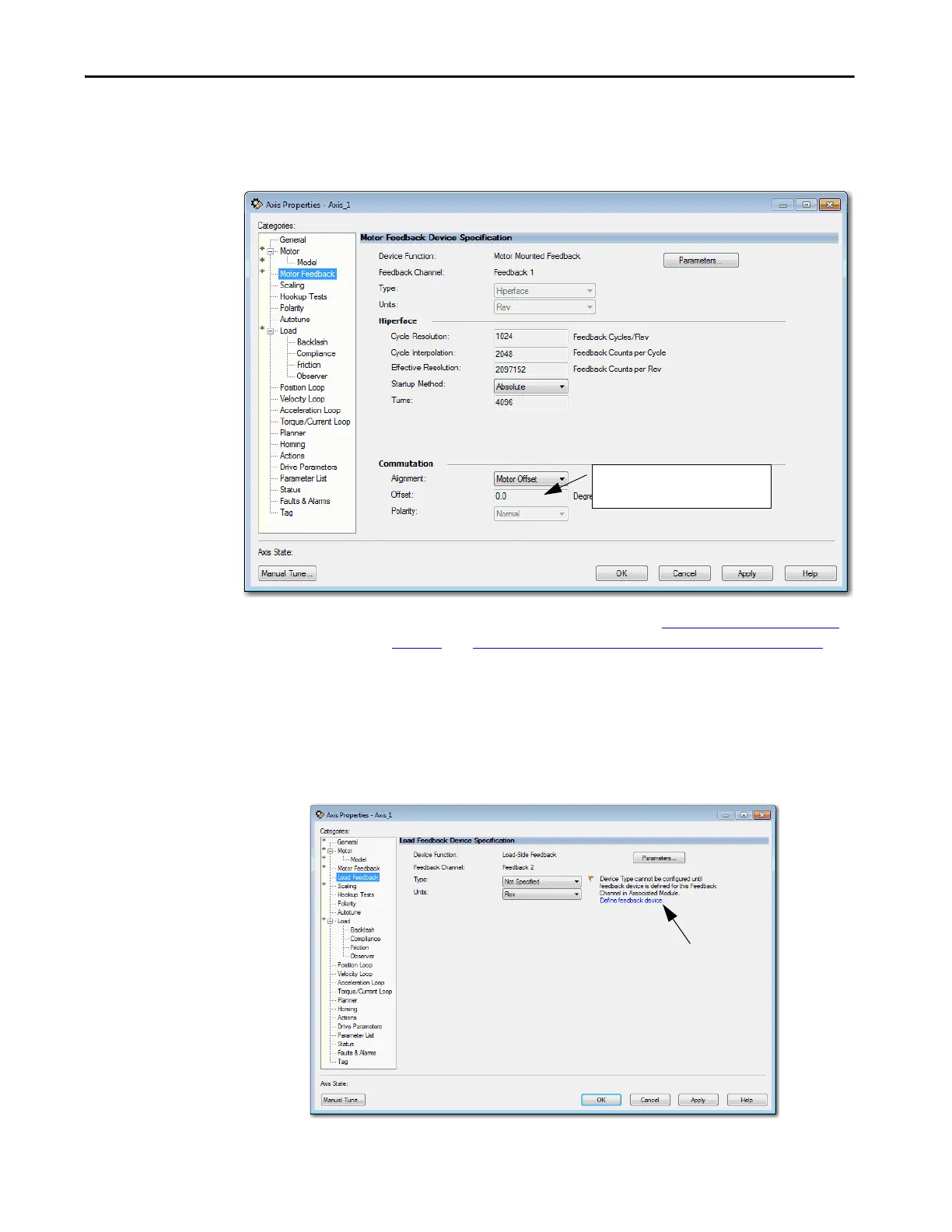
On the Motor Feedback dialog box, the information is automatically
filed in based on your selections on the Motor dialog box.
Figure 29 - Example 2: Position Loop with Dual Feedback, Motor Feedback Dialog Box
For information about Commutation, see Assign Motor Feedback on
page 54 and Applying the Commutation Hookup Test on page 232.
The axis is now configured as the primary feedback. The next task is to
configure Feedback 2 on the Load Feedback dialog box.
6. To assign the Load Feedback device, click the Define feedback device
hyperlink or go to the Module Properties of the drive.
Figure 30 - Example 2: Position Loop with Dual Feedback, Load Feedback Dialog Box, Load-side
Feedback
The drive gets the commutation that is
offset directly from the motor.

 Loading...


