Rockwell Automation Publication MOTION-UM003K-EN-P - January 2019 193
Axis Configuration Examples for the PowerFlex 755 Drive Chapter 9
6. Choose the Commutation Alignment.
For more information about Commutation, see Applying the
Commutation Hookup Test on page 232.
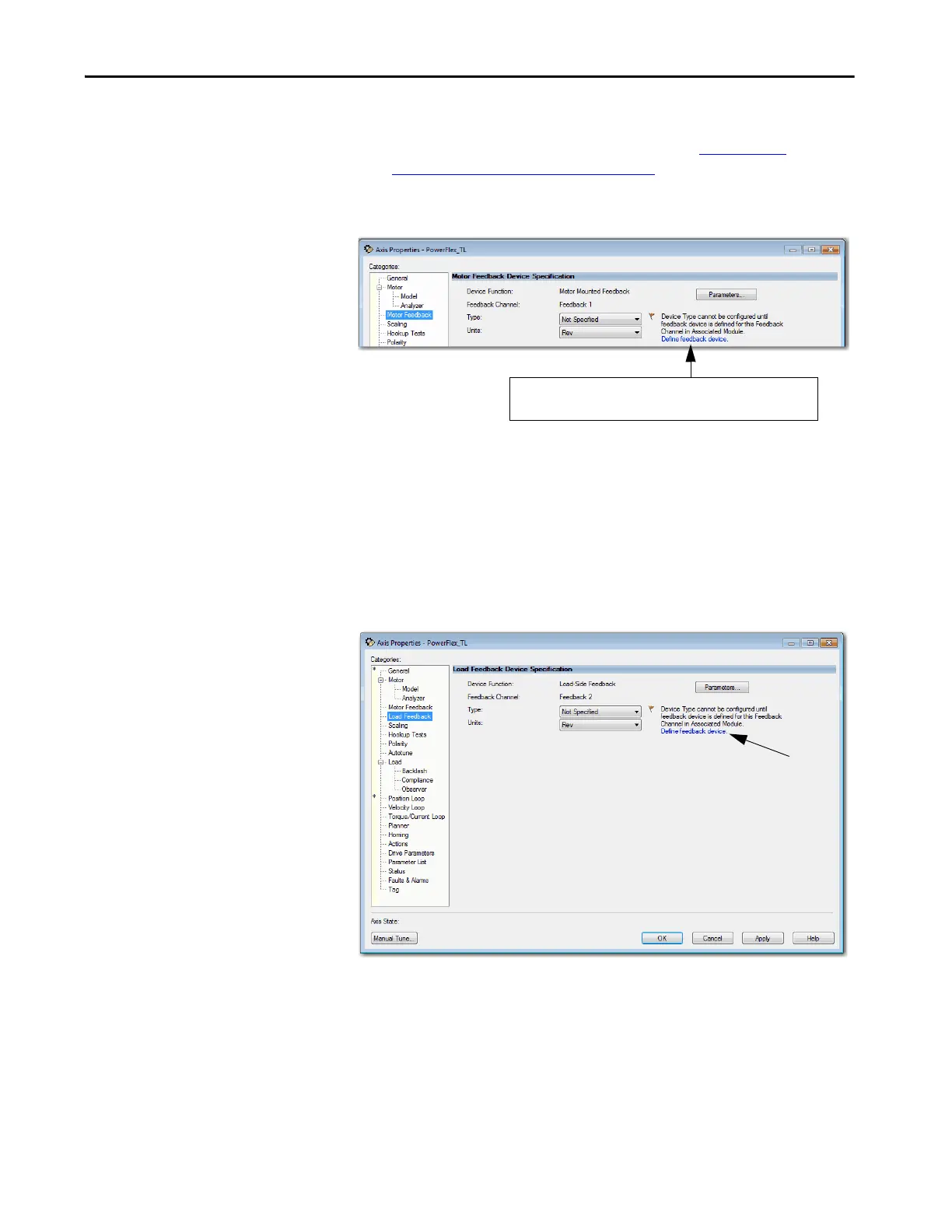
On the Motor Feedback dialog box, the information is automatic based
on your selections on the Motor dialog box.
The axis is now configured as a Position Loop with two feedback
devices. The next task is to configure Feedback 2 on the Load Feedback
dialog box.
Follow these instructions to define the Load feedback.
1. From the Load Feedback dialog box, click the Define feedback device
hyperlink.
Figure 62 - Example 2: Load-side Feedback, Load Feedback Dialog Box
If you have not defined a feedback device, the motor dialog box
displays a link to the module definition for the drive.

 Loading...


