194 Rockwell Automation Publication MOTION-UM003K-EN-P - January 2019
Chapter 9 Axis Configuration Examples for the PowerFlex 755 Drive
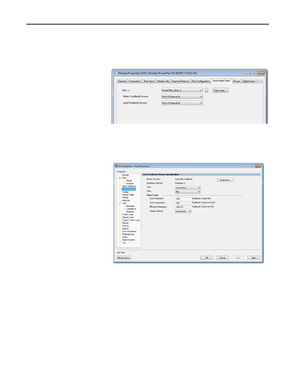
2. Click Associated Axes in Module Properties dialog box.
3. From the Load Feedback Device pull-down menu, choose the
appropriate port/channel for the Load Feedback Device.
Figure 63 - Example 2: PowerFlex 755 Module Properties, Associated Axis Tab
4. From the Type pull-down menu, choose the type of feedback.
5. From the Units pull-down menu, choose the appropriate units.
6. Click Apply.
Figure 64 - Example 2: Load-side Feedback, Load Feedback Dialog Box

 Loading...


