78 Rockwell Automation Publication MOTION-UM003K-EN-P - January 2019
Chapter 4 Configure Integrated Motion Control Using Kinetix 5700 Drives
7. The connection between the owner and the 2198-xxxx-ERSx inverter is
based on the following:
• Servo drive safety network number
•GuardLogix slot number
• GuardLogix safety network number
• Path from the GuardLogix controller to the 2198-xxxx-ERSx drive
• Configuration signature
If any differences are detected, the connection between the GuardLogix
controller and the 2198-xxxx-ERSx inverter is lost, and the yellow yield
icon appears in the controller project tree after you download the
program.
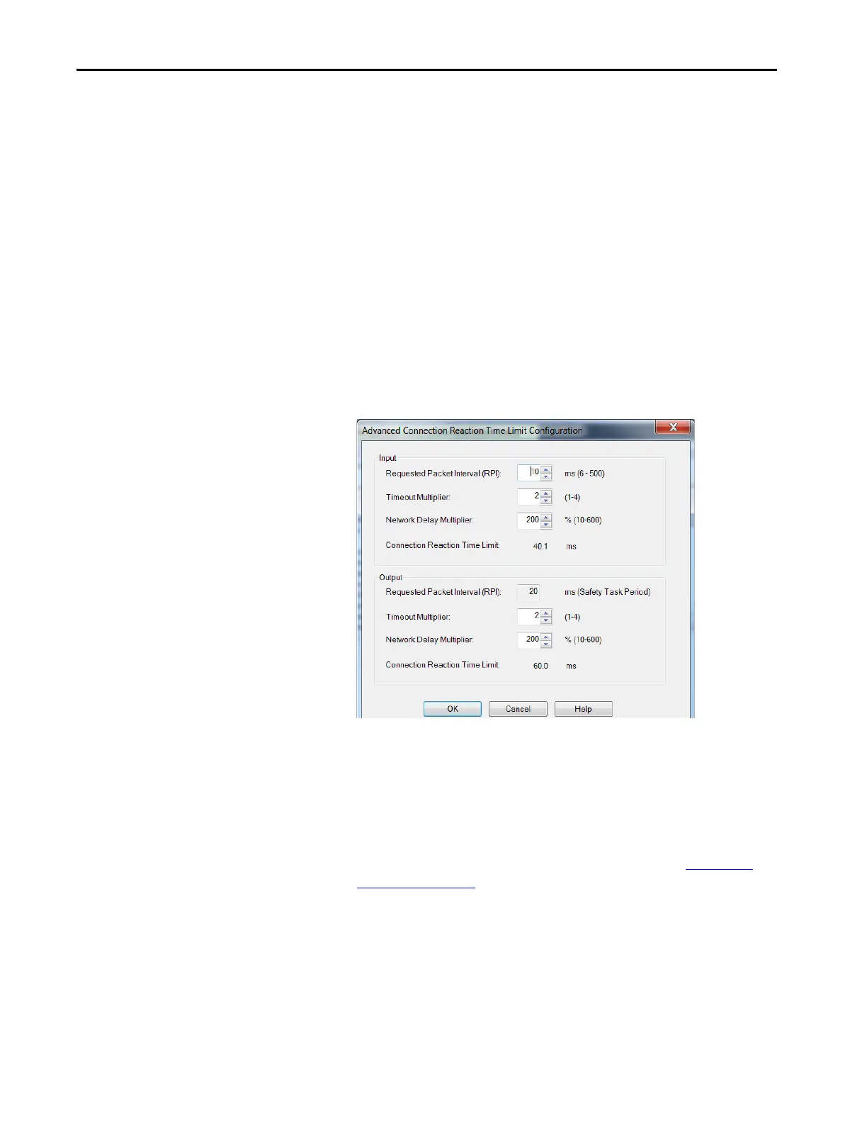
8. Click Advanced.
The Advanced Connection Reaction Time Limit Configuration dialog
box appears.
Analyze each safety channel to determine the appropriate settings. The
smallest Input RPI allowed is 6 ms. The selection of small RPI values
consumes network bandwidth and can cause spurious trips because
other devices cannot get access to the network.
For more information about the Advanced Connection Reaction Time
Limit Configuration, refer to the appropriate GuardLogix or Compact
GuardLogix Controllers User Manual, which is listed in Additional
Resources on page 9.
9. To close the Advanced dialog box, click OK.
10. To save the Safety category parameters, click apply.

 Loading...


