EasyManuals Logo

Allen-Bradley PowerFlex 755 User Manual

Allen-Bradley PowerFlex 755
354 pages
To Next Page IconTo Next Page
To Previous Page IconTo Previous Page
Page #147 background imageLoading...
Page #147 background image
Rockwell Automation Publication MOTION-UM003K-EN-P - January 2019 147
Axis Scheduling Chapter 7
Timing Model
The general timing model for the integrated motion on the EtherNet/IP
network I/O connection data exchange is described in this section. The
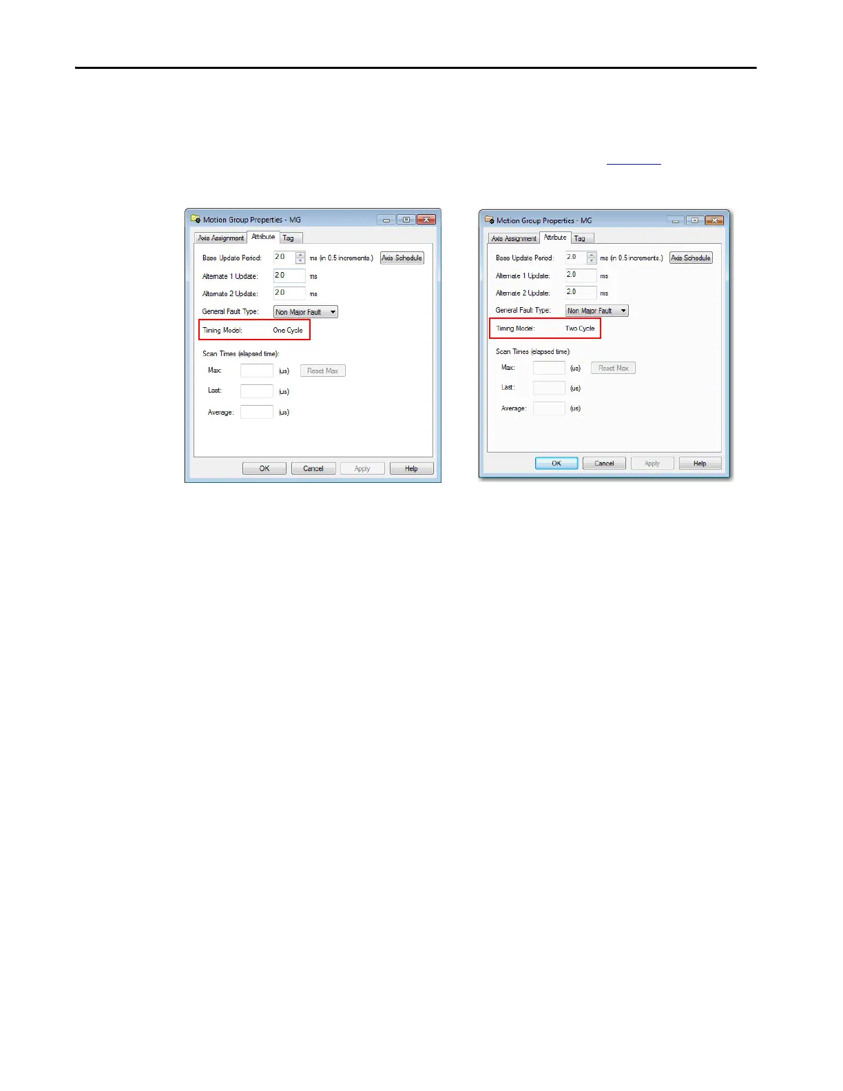
Timing Model field on the Attribute tab of the Motion Group Properties
dialog box is shown as One Cycle or Two Cycle. See Figure 21
for an example.
Figure 21 - Timing Model Attribute Examples

Table of Contents

Other manuals for Allen-Bradley PowerFlex 755

Questions and Answers:

Question and Answer IconNeed help?

Do you have a question about the Allen-Bradley PowerFlex 755 and is the answer not in the manual?

Allen-Bradley PowerFlex 755 Specifications

General IconGeneral
CategoryAC Drive
Amperage2.2…1470 A
Output Voltage0 to Input Voltage
Output Current2.2…1470 A
EnclosureIP20, IP30, IP54
CommunicationsEtherNet/IP, ControlNet, DeviceNet
I/ODigital, Analog, Encoder, Relay
SafetySafe Speed Monitor
Protection FeaturesOvercurrent, Overvoltage, Undervoltage, Overload, Short Circuit, Ground Fault, Overtemperature
Operating Temperature-10°C to 50°C (14°F to 122°F)
Storage Temperature-40°C to 70°C (-40°F to 158°F)
Humidity5…95% noncondensing
AltitudeUp to 1000m (3300ft) without derating
Voltage200-240V AC, 380-480V AC, 500-600V AC, 690V AC
Input Voltage200-240V AC, 380-480V AC, 500-600V AC, 690V AC
Control MethodSensorless Vector

Related product manuals