Rockwell Automation Publication MOTION-UM003K-EN-P - January 2019 245
Commission an Axis Chapter 11
For the purposes of this manual, resonances are characterized as follows:
• HF resonances are above the low frequency limit
• LF resonances are below the low frequency limit
• MF resonances are slightly above the low frequency limit
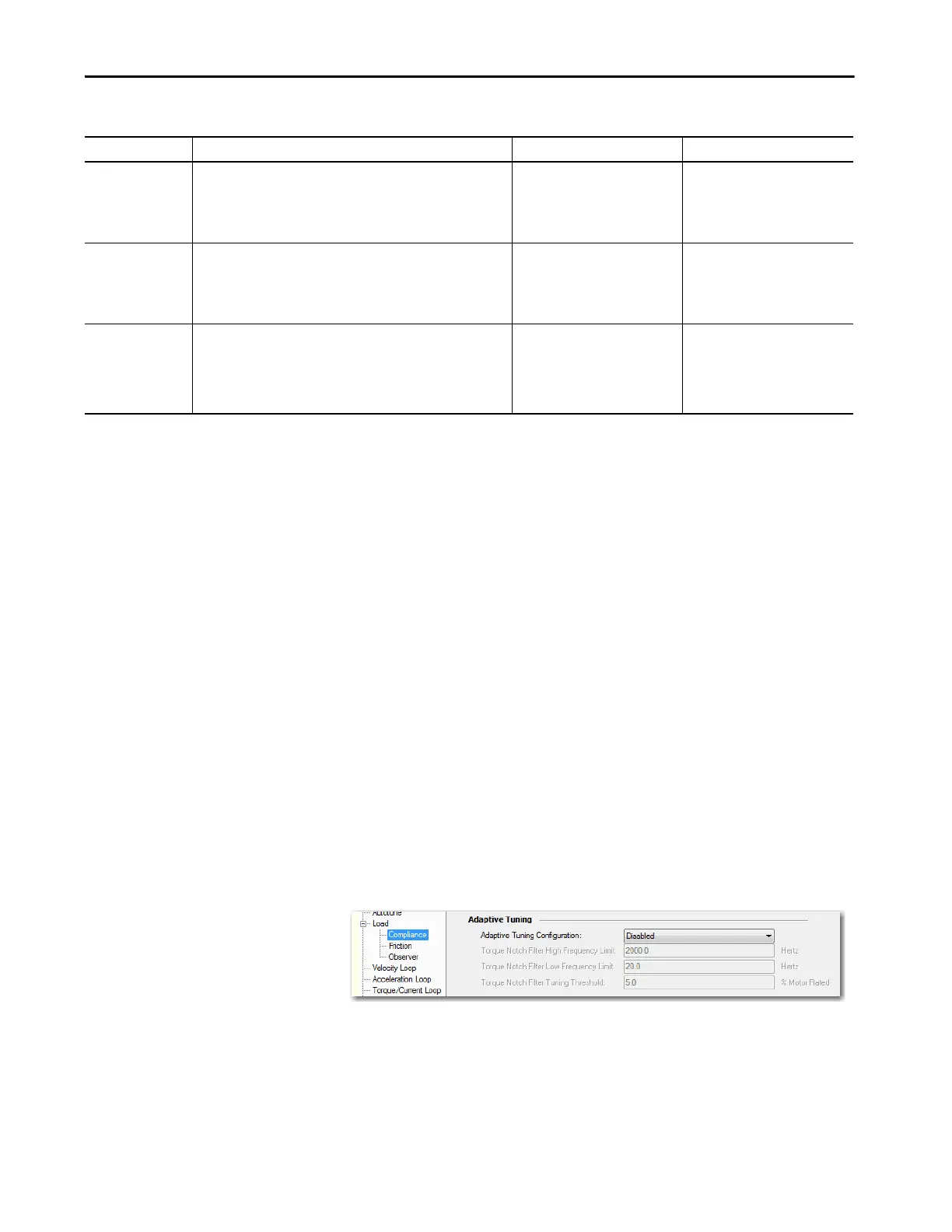
Adaptive Tuning Configuration
The modes of adaptive tuning operation include:
•Disabled
•Notch Filter Tuning
• Gain Stabilization
• Notch Filter Tuning and Gain Stabilization
You access adaptive tuning from the Compliance tab on the Load Category
page.
Disabled
As previously stated, Adaptive Tuning is always running in the background to
identify motor side resonances, even when the feature is disabled.
No action is taken to compensate for the identified resonances in this mode.
The result is status only, which lets you create custom Ladder Logic to react to
changes. This function is useful for condition monitoring, diagnostics, and
preventative maintenance purposes in tracking HF resonances that changes
over time. In Disabled mode, the high frequency limit, low frequency limit,
and turning threshold are dim. As a result, you have to enable Adaptive Tuning
Torque Low Pass Filter
Bandwidth Estimate
In modes with Gain Stabilization, Adaptive Tuning incrementally
decreases this bandwidth estimate from its default value in 200 Hz
increments to suppress additional resonances above the low frequency
limit if necessary. Additional resonances are resonances that notch
filters do not already suppress.
Torque Low Pass Filter BW or 1500
when disabled
20…2000 Hz
Adaptive Tuning Gain
Scaling Factor
In modes with Gain Stabilization, Adaptive Tuning incrementally
decreases this gain scaling factor from its default value to stabilize the
system if necessary. Resonances that not already suppressed by filters or
caused by filter bandwidths that are too close to the closed-loop
bandwidth cause instability.
1 0 - max float
Adaptive Tuning
Configuration
Controls the Adaptive Tuning feature mode of operation. Disabled 0 = Disabled
1 = Tracking Notch Filter
2 = Gain Stabilization
3 = Tracking Notch Filter and Gain
Stabilization
Table 51 - Adaptive Tuning Attributes
Parameter Name Description Default Value Range/Units
 Loading...


