Rockwell Automation Publication MOTION-UM003K-EN-P - January 2019 247
Commission an Axis Chapter 11
• Position Loop Integrator Bandwidth
The actual control loop gains are the values that are shown in the Axis
Properties dialog box multiplied by the gain scaling factor. The scaling factor is
incrementally decreased from its default value until the system is stable. When
Gain Stabilization is not enabled, the scaling factor is reset to its default value
of 1 so that control loop gains are not affected.
Gain Stabilization is good for situation where there are more resonances than
there are notch filters and for keeping the axis stable. Instability and audible
noise is caused from the following situations:
• HF resonances that filters do not already suppress
• MF resonances that filters suppress where the filter bandwidths are too
close to the closed-loop bandwidth
• LF resonances that result when Load Observer is not applied with the
recommended out-of-box settings
• LF resonances that result from classical instability
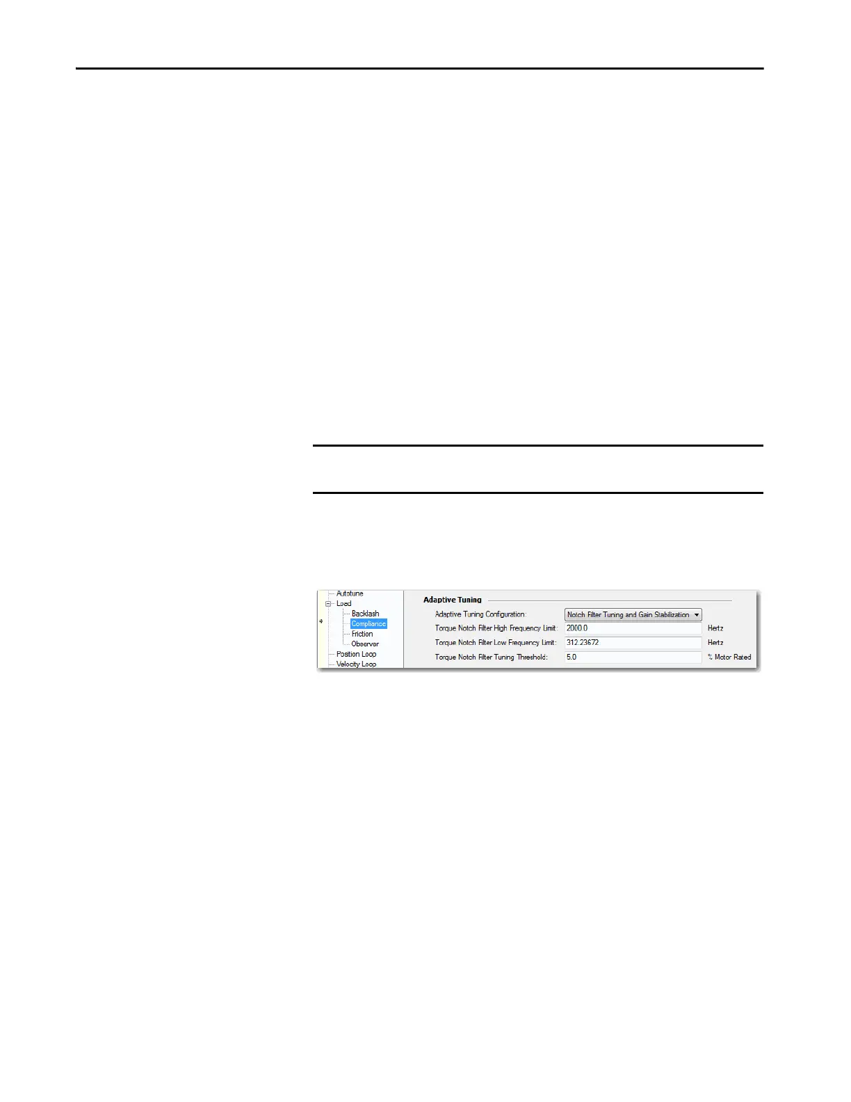
Notch Filter Tuning and Gain Stabilization
Adaptive Tuning applies the Notch Filter Tuning if necessary, followed by
Gain Stabilization, if necessary.
Notch Filter Tuning sets the torque notch filter to suppress an HF resonance
with the largest magnitude if one exists. Gain Stabilization applies the low pass
filter to suppress additional HF resonances if they exist. This function is useful
for suppressing more HF resonances than there are notch filters. If the system is
unstable, Gain Stabilization incrementally detunes control loops until the
system is stable.
The torque notch filter is set to suppress it if it is the only HF resonance or if it
is the once with the largest magnitude. If not, the low pass filter is set to
suppress it and any other HF resonances. The system is detuned if one or more
of the following conditions exist:
• The torque notch filter was set to suppress the MF resonance. The width
of the torque notch filter is wide enough or its frequency is close enough
to the closed-loop bandwidth to cause instability
• The torque low pass filter was set to suppress the MF resonance, but its
bandwidth is close enough to the closed-loop bandwidth to cause
instability
IMPORTANT We do not recommend that you enable Gain Stabilization on vertical loads
as detuning can cause load drops.

 Loading...


