EasyManuals Logo

Allen-Bradley PowerFlex 755 User Manual

Allen-Bradley PowerFlex 755
354 pages
To Next Page IconTo Next Page
To Previous Page IconTo Previous Page
Page #170 background imageLoading...
Page #170 background image
170 Rockwell Automation Publication MOTION-UM003K-EN-P - January 2019
Chapter 8 Configuration Examples for a Kinetix Drive
7. To apply your changes and return to Axis Properties, click OK.
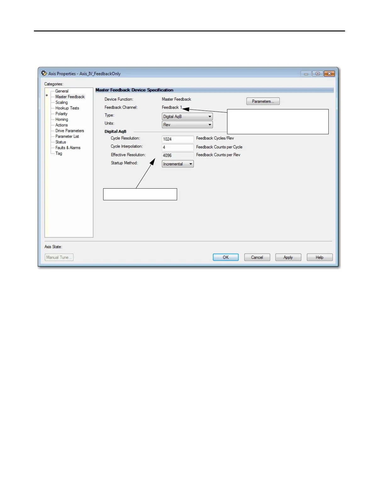
Figure 37 - Example 3: Feedback Only with Master Feedback, Master Feedback Dialog Box
8. From the Type pull-down menu, choose Digital AqB as the feedback
type.
9. From the Units pull-down menu, choose Rev.
Default values are completed for you.
This channel is Feedback 1 of Axis 2. It is connected to
the Aux Feedback port of the primary axis. This
Feedback-only axis is also known as the 1/2 axis.

Table of Contents

Other manuals for Allen-Bradley PowerFlex 755

Questions and Answers:

Question and Answer IconNeed help?

Do you have a question about the Allen-Bradley PowerFlex 755 and is the answer not in the manual?

Allen-Bradley PowerFlex 755 Specifications

General IconGeneral
CategoryAC Drive
Amperage2.2…1470 A
Output Voltage0 to Input Voltage
Output Current2.2…1470 A
EnclosureIP20, IP30, IP54
CommunicationsEtherNet/IP, ControlNet, DeviceNet
I/ODigital, Analog, Encoder, Relay
SafetySafe Speed Monitor
Protection FeaturesOvercurrent, Overvoltage, Undervoltage, Overload, Short Circuit, Ground Fault, Overtemperature
Operating Temperature-10°C to 50°C (14°F to 122°F)
Storage Temperature-40°C to 70°C (-40°F to 158°F)
Humidity5…95% noncondensing
AltitudeUp to 1000m (3300ft) without derating
Voltage200-240V AC, 380-480V AC, 500-600V AC, 690V AC
Input Voltage200-240V AC, 380-480V AC, 500-600V AC, 690V AC
Control MethodSensorless Vector

Related product manuals