EasyManuals Logo

Allen-Bradley PowerFlex 755 User Manual

Allen-Bradley PowerFlex 755
354 pages
To Next Page IconTo Next Page
To Previous Page IconTo Previous Page
Page #201 background imageLoading...
Page #201 background image
Rockwell Automation Publication MOTION-UM003K-EN-P - January 2019 201
Axis Configuration Examples for the PowerFlex 755 Drive Chapter 9
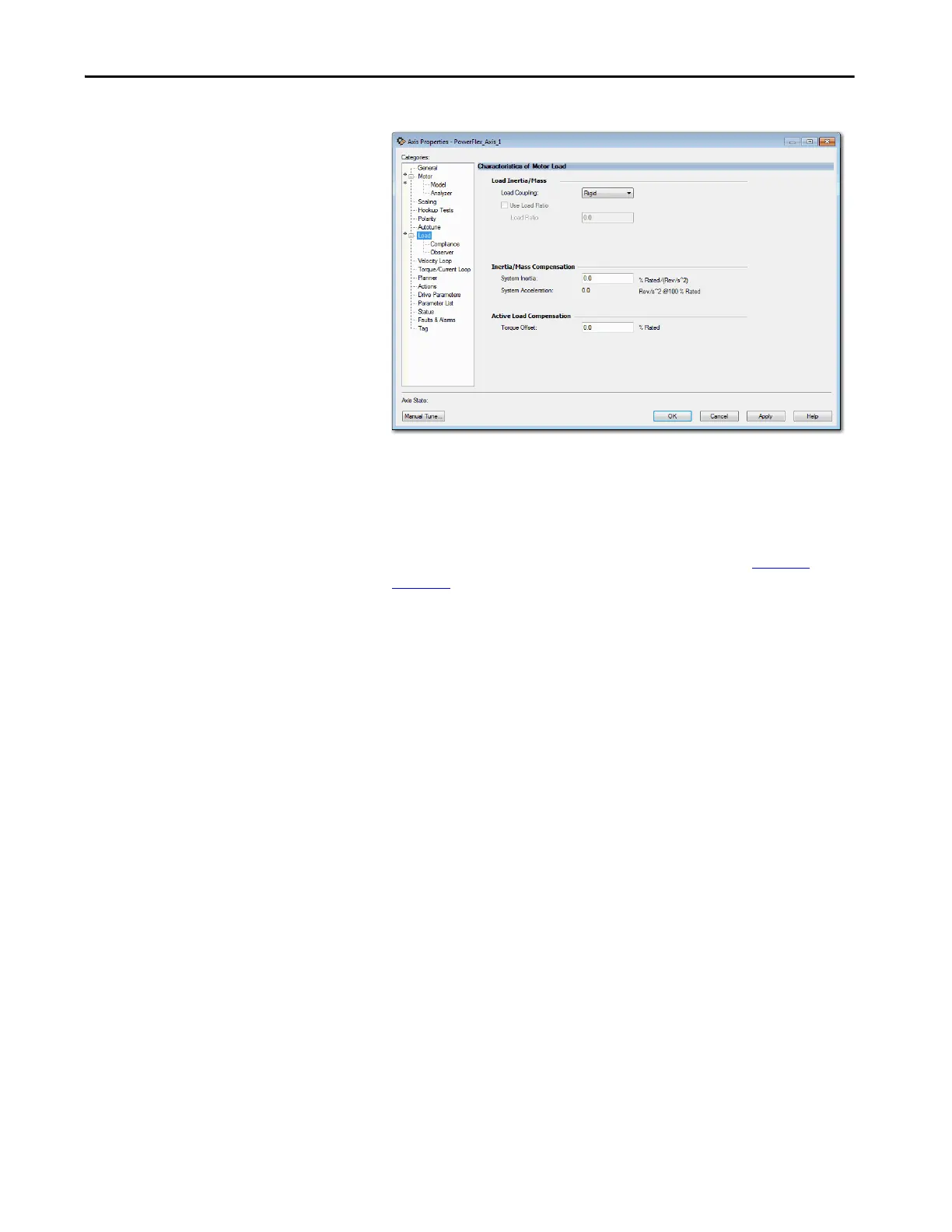
Figure 74 - Example 4: Velocity Loop with No Feedback, Load Dialog Box
8. From the Load Coupling pull-down menu, choose the appropriate load
coupling.
9. Enter the System Inertia.
10. Enter the Torque Offset, if applicable.
For more information about the load characteristics, see Load on
page 239.
11. Click Apply.
You are now finished configuring an axis as Velocity Loop with No Feedback.

Table of Contents

Other manuals for Allen-Bradley PowerFlex 755

Questions and Answers:

Question and Answer IconNeed help?

Do you have a question about the Allen-Bradley PowerFlex 755 and is the answer not in the manual?

Allen-Bradley PowerFlex 755 Specifications

General IconGeneral
CategoryAC Drive
Amperage2.2…1470 A
Output Voltage0 to Input Voltage
Output Current2.2…1470 A
EnclosureIP20, IP30, IP54
CommunicationsEtherNet/IP, ControlNet, DeviceNet
I/ODigital, Analog, Encoder, Relay
SafetySafe Speed Monitor
Protection FeaturesOvercurrent, Overvoltage, Undervoltage, Overload, Short Circuit, Ground Fault, Overtemperature
Operating Temperature-10°C to 50°C (14°F to 122°F)
Storage Temperature-40°C to 70°C (-40°F to 158°F)
Humidity5…95% noncondensing
AltitudeUp to 1000m (3300ft) without derating
Voltage200-240V AC, 380-480V AC, 500-600V AC, 690V AC
Input Voltage200-240V AC, 380-480V AC, 500-600V AC, 690V AC
Control MethodSensorless Vector

Related product manuals