62 Rockwell Automation Publication MOTION-UM003K-EN-P - January 2019
Chapter 4 Configure Integrated Motion Control Using Kinetix 5700 Drives
6. From the pull-down menus, choose the power options appropriate for
your actual hardware configuration.
7. To close the New Module dialog box, click OK.
8. To close the Select Module Type dialog box, click Close.
9. Right-click the DC-bus power supply that you created in the Controller
Organizer and choose Properties.
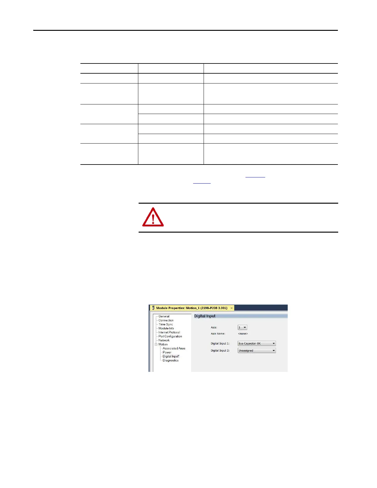
The Module Properties dialog box appears.
10. Click the Digital Input category.
11. From the Digital Input pull-down menu, choose Bus Capacitor OK to
monitor your capacitor module status. Alternately, choose Thermal
Switch OK to monitor your shunt thermal switch. You can also choose
Bus Conditioner OK to monitor your conditioner monitor status, but
this option is only available in major revision 10 or later.
In this example, Bus Capacitor OK is chosen.
Attribute Menu Description
Bus Configuration Shared AC/DC
(1)
Applies to 2198-Pxxx DC-bus power supply (converter) modules.
Bus-sharing Group
(2)
•Group1
•Group2
•Group3…
Applies to any bus-sharing configuration.
Bus Regulator Action
Disabled Disables the internal shunt resistor and external shunt option.
Shunt Regulator Enables the internal and external shunt options.
Shunt Regulator Resistor Type
Internal Enables the internal shunt (external shunt option is disabled).
External Enables the external shunt (internal shunt option is disabled).
External Shunt
(3)
•None
• 2198-R004, 2198-R014
• 2198-R031, 2198-R127
Selects external shunt option. Only the shunt catalog number intended for
the specific DC-bus power supply is shown.
(1) Shared AC/DC bus configuration is the default selection for DC-bus power supplies.
(2) For more information on bus-sharing groups, refer to Kinetix 5700 servo drives User Manual, publication 2198-UM002
.
(3) See the Kinetix Servo Drives Specifications Technical Data, publication KNX-TD003
, for more information on the Bulletin 2198 external passive shunt resistors.
ATTENTION: To avoid damage to equipment all modules that are physically
connected to the same shared-bus connection system must be part of the
same Bus-sharing Group in the Studio 5000 Logix Designer application.

 Loading...


