Rockwell Automation Publication MOTION-UM003K-EN-P - January 2019 79
Configure Integrated Motion Control Using Kinetix 5700 Drives Chapter 4
Configure Digital Inputs
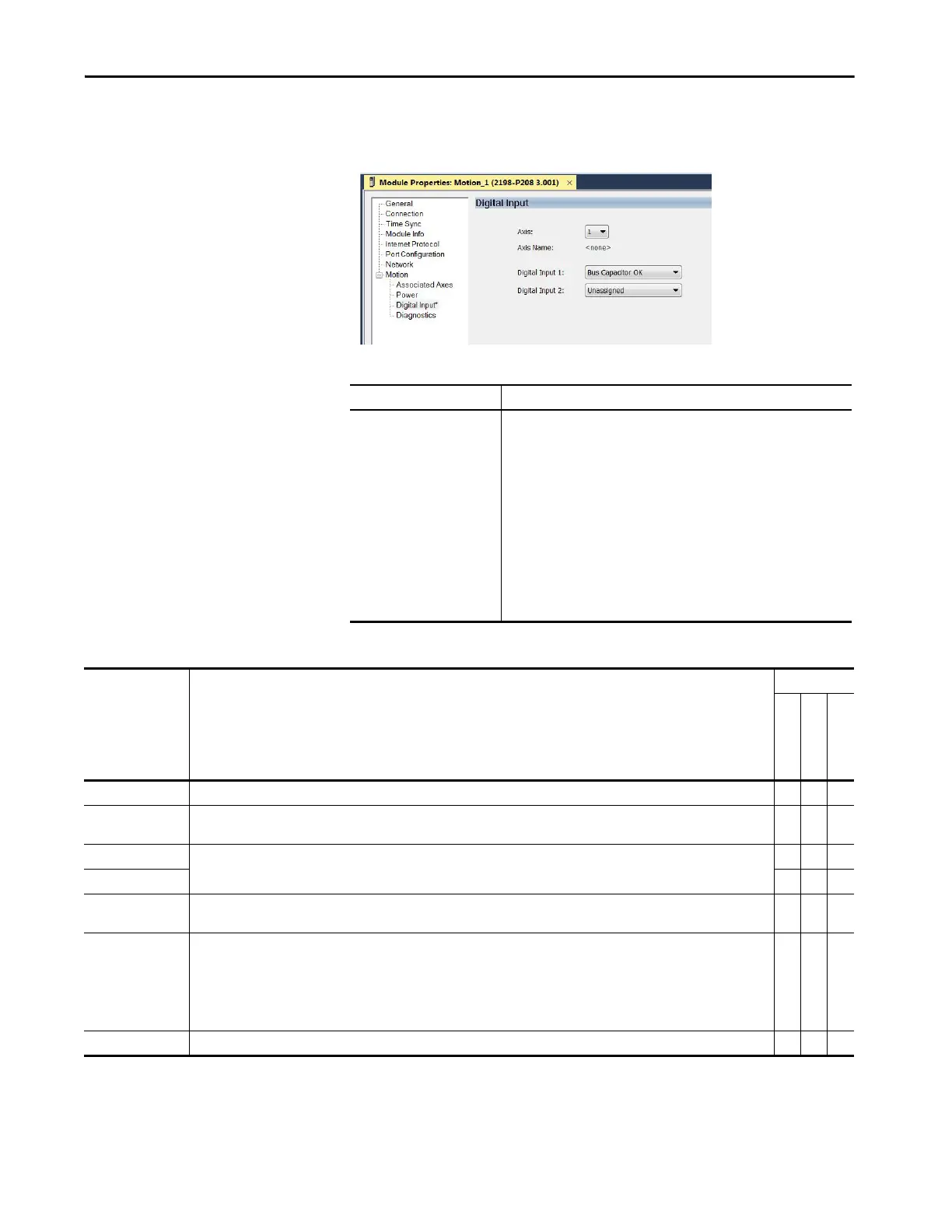
Figure 8 - Digital Input Tab for the Kinetix 5700 Drive
Table 22 - Understand Digital Input Functions
Table 21 - Module Properties: Kinetix 5700 Digital Input Tab Descriptions
Parameter Description
Digital Input 1
Digital Input 2
Digital Input 3
Digital Input 4
Choose one of these values for Digital Input 1 and 2:
• Unassigned
•Enable
• Home
• Registration 1
• Registration 2
• Positive Overtravel
• Negative Overtravel
• Regeneration OK
• AC Line Contactor OK
•Bus Capacitor OK
• Bus Conditioner OK
•Shunt Thermal Switch OK
Functions Description
Drive Module
2198-Pxxx
2198-xxxx-ERSx
2198-RPxxx
Enable A 24V DC input is applied to this terminal as a condition to enable each module. X X X
Home
An active state indicates to a homing sequence that the referencing sensor has been seen. Typically, a transition of this signal is used to
establish a reference position for the machine axis.
–X–
Registration 1
An inactive-to-active transition (also known as a positive transition) or active-to-inactive transition (also known as a negative
transition) is used to latch position values for use in registration moves.
–X–
Registration 2 –X–
Positive Overtravel
Negative Overtravel
The positive/negative limit switch (normally closed contact) inputs for each axis require 24V DC (nominal). – X –
Regeneration OK
In the active state the inverters can be enabled. An inactive state indicates that the Bulletin 8720MC-RPS unit is not ready to supply DC-
bus power. The inverters cannot be enabled.
When a bus group is supplied by an 8720MC-RPS unit, one inverter in the bus group must be configured in the Logix Designer
application as Shared-DC Non-CIP Motion™ Converter and assigned to Regeneration OK. This signal is wired from RDY on the
8720MC-RPS unit and indicates to the Kinetix 5700 drive system that the 8720MC-RPS unit is ready to supply power. Enabled inverters
enumerate a Bus Power Sharing fault if the Regeneration OK input goes inactive.
–X–
AC Line Contactor OK An active indicates that the AC Line Contactor is working correctly and is capable of charging the DC bus. X

 Loading...


