Design and function
Application and area of usage
760.0002 GB - 150 500
BA-2011.11
Series AE1F, AE1L, AE.E, AE.N, AE.H, AE.V, AED1E,
AED2N ID, ZD construction types
7
4 Design and function
4.1 Application and area of usage
Progressing cavity pumps are self-priming,
rotating displacement pumps suitable for
pumping and metering low-viscosity and high-
viscosity liquids, neutral or aggressive liquids,
undiluted or abrasive liquids, liquids containing
gases, liquids prone to foaming, and liquids
with fibrous or solid particles.
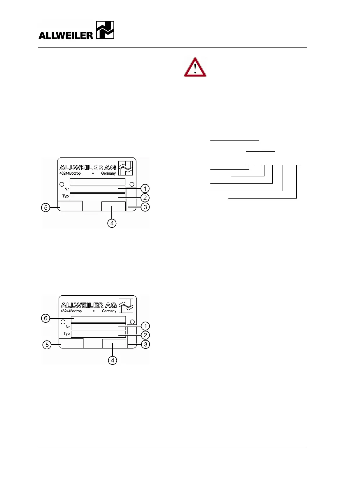
4.2 Labeling
4.2.1 Nameplate
Fig. 1 Nameplate (example)
1 Pump number
2 Pump model
3 Direction of rotation or pumping
4 Direction of rotation or pumping
5 CE Mark, Year of Manufacture
4.2.2 ATEX nameplate
Fig. 2 ATEX nameplate
1 Pump number
2 Pump model
3 Direction of rotation or pumping
4 Direction of rotation or pumping
5 CE Mark, Year of Manufacture
6 Explosion Protection Designation
Danger!
If the pump or pump unit is
operated in potentially explosive
atmospheres, follow the ATEX
supplemental instructions.
4.2.3 Pump model label
The model code for progressing cavity pumps
has several components, as shown in this
example:
Series
A E 1 E 100 – ID
A E 1 N 200 – ZD
Product
Number of stages
Mechanics
Size
Construction type
Fig. 3 Model code
This model code is engraved on the
nameplate.
4.3 Performance data
Refer to the order data sheet for the exact
performance data applicable to the pump.
4.4 Design
4.4.1 Structural design
Self-priming single, double, quadruple, or
eight-stage progressing cavity pump. Pumping
elements are the rotor and stator. A coupling
transfers the drive torque to the drive shaft, the
universal joint shaft, and the rotor.
External housing connection screws (clamp
bolts) hold together the discharge casing,
stator, and suction casing.
The stuffing box or mechanical seal casing is
located between the suction casing and the
bearing bracket.
4.4.2 Bearing and lubrication
Both sides of the drive shaft have liquid-sealed
encapsulated pin joints. Lubrication is provided
by joint oil.
The drive shaft bearings are angular contact
and groove ball bearings located in the bearing
bracket. The bearings are protected against
spray water.
 Loading...


