Maintenance
Disassembly and assembly instructions
28
Series AE1F, AE1L, AE.E, AE.N, AE.H, AE.V, AED1E,
AED2N ID, ZD construction types
BA-2011.11
760.0002 GB - 150 500
10.1.4 Removing the universal joint
shaft and the drive-side joint
For the positions of referenced parts
sectional drawings on pages 43, 44, 45, 46,
47, 48, and 49.
Remove the universal joint shaft and the drive-
side joint after removing the stator (402) and
the rotor (401) section 10.1.2 page 26 and
10.1.3 page 26.
1. Disassemble the drive-side joint as
described under section 6 .
2. Pull off the universal joint shaft (307)
from the drive shaft (118).
3. Push out the joint bush (302) from the
universal joint shaft (307).
4. Use a brass punch to fully drive out the
bush for the universal joint shaft (303)
from the drive shaft (118).
10.1.5 Removing the shaft seal and
drive shaft
Notice!
When a pump uses a stuffing box
for the shaft seal, the packing rings
section 9.1.4.1 page 23 can be
replaced without removing the drive
shaft. Removal of the drive shaft is
essential when the pump is
equipped with a mechanical seal. If
the drive shaft or shaft sleeve are
damaged near the shaft seal, the
pump must be disassembled as
described below.
1. Remove stator (402) ( Section 6
page 26).
2. Remove hexagon nut (607), serrated
washer (608), and hexagon screw
(606).
3. Pull off suction casing (505) over the
rotor (401).
Caution!
The rotor is manufactured to close
tolerances. Make sure it is not
damaged.
4. Remove the seal for the suction case
(501).
5. Pull off coupling half or belt pulley and
remove the key (101).
6. Screw out hexagon screw (139) and
remove bearing cover (131) with seal
(132).
7. Screw off the bearing nut (116) from
the drive shaft (118).
8. Press the drive shaft (118) with
attached to rotor (401), attached
universal joint shaft (307), and
installed shaft seal from the bearing
bracket (110).
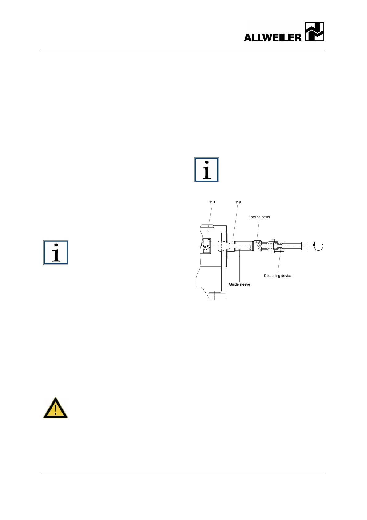
9. To do this, apply extraction device to
bearing bracket (110) (see image
below).
Notice!
Guide sleeve and pressure shaft
are assembly aids that can be
obtained from us.
Fig. 12 Pressing out the drive shaft
10. Pull off the thrower (114) from the
drive shaft (118).
10.1.6 Removing the stuffing box
For the positions of referenced parts
sectional drawings on pages 43, 44, 45, 46,
47, 48, and 49.
1. Remove self-locking hexagon nut
(202) and take off both halves of the
stuffing box gland (203).
2. Pull off the stuffing box casing (204)
from the drive shaft (118).
3. Remove the following from the stuffing
box casing (204): the gland packing
(207) on versions P02, P12 including
flushing ring (208); including seal
chamber ring (209) on versions P03,
P13 and P04, P14.