Maintenance
Assembling the progressing cavity pump
760.0002 GB - 150 500
BA-2011.11
Series AE1F, AE1L, AE.E, AE.N, AE.H, AE.V, AED1E,
AED2N ID, ZD construction types
33
handling and extreme cleanliness are required
during installation to ensure flawless
functionality. To facilitate installation, surfaces
over which O-rings glide may be lubricated
with silicon oil, polydiol, or lubricating soap, for
example.
Caution!
Do not use petroleum-based or
synthetic oil as a lubricant!
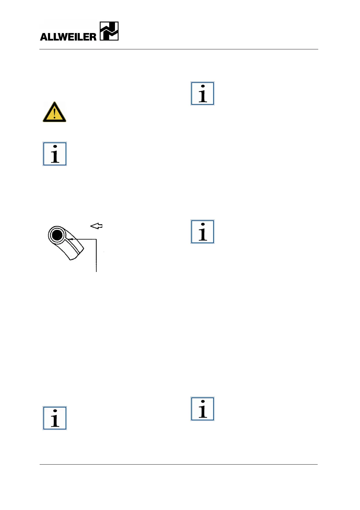
Notice!
Always replace in pairs those parts
that glide over each other. When
using double PTFE-encased O-
rings, make sure that the joint of the
outermost encasement points
against the direction of installation.
Otherwise the encasement may
open and pull off ( see next
image).
Fig. 15 Joint of the outermost encasement points
against the direction of installation
10.2.2.3 Installing the mechanical seal,
single-acting
For the positions of referenced parts
sectional drawings on pages 43, 44, 45, 46,
47, 48, and 49.
1. Drive the locking pin (220) into the
mechanical seal casing (214).
2. Concentrically press the mechanical
seal's counterring (219) with O-ring
into the clean mechanical seal casing
(214).
Notice!
Always use uniform pressure
distribution on the locking pin. The
locking pin (220) may not protrude
inwards.
3. Slide the rotating part of the
mechanical seal (219) onto the drive
shaft (118).
Notice!
Observe precisely the installation
dimension and position of the
mechanical seal (as marked during
removal).
4. If threaded pins are present, insert
them into the rotating part of the
mechanical seal (219) and screw them
in place with Loctite No. 241 or a
comparable product.
5. Slide the mechanical seal casing (214)
with the mechanical seal counterring
(219) over the drive shaft (118).
Notice!
To avoid damaging the mechanical
seal counterring, make sure that
the mechanical seal casing does
not become canted when sliding it
onto the drive shaft.
10.2.2.4 Installing the mechanical seal,
single-acting with quench
For the positions of referenced parts
sectional drawings on pages 43, 44, 45, 46,
47, 48, and 49.
1. Install the mechanical seal as
described under the section "Installing
the mechanical seal, single-acting" (
section 10.2.2.3 page 33).
2. Drive in the locking pin (220) and
utilize sealing material (251) Loctite
No. 640 or a similar product.
3. Press the shaft seal ring (232) into the
clean mechanical seal casing (214).
Do not grease the sealing lip.
Notice!
The sealing lip of the shaft seal ring
must always face the side being
sealed (pointing inward).
Use a suitable pressing die to press
it inward. It is extremely important
that the pressing force be applied
as close to the outer diameter of
the shaft seal ring as possible.
Assembly direction
Seam of the outer teflon
coating
 Loading...


