Maintenance
Assembling the progressing cavity pump
32
Series AE1F, AE1L, AE.E, AE.N, AE.H, AE.V, AED1E,
AED2N ID, ZD construction types
BA-2011.11
760.0002 GB - 150 500
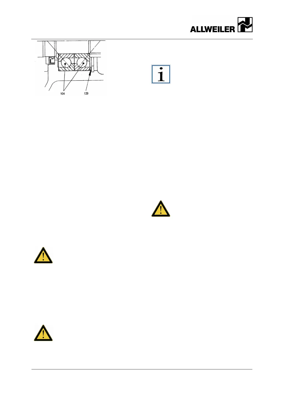
Fig. 14 Two single-row angular contact ball bearings
with spacer rings
5. Insert circlip (127) into the bearing
bracket (110) before the ball bearing
(104) or the spacer rings (129),
respectively.
6. Insert spacer sleeve (102) into the
bearing bracket (110).
7. Fill about 90% of the space between
the bearing bracket (110) and spacer
sleeve (102) with antifriction bearing
grease.
• The antifriction bearing grease
we recommend section
9.1.3 page 22 .
• Filling volume Table 9.1.7
page 25.
8. Use a suitable section of pipe to push
the greased groove ball bearing (103)
from the drive side over the bearing
outer ring into the bearing bracket
(110). First apply a thin coating of oil to
the bearing surface.
Caution!
If the pump is horizontally
installed, the sealing washer used
in the groove ball bearing must
point to the drive side!
Vertically installed pumps with the
bearing on top have groove ball
bearing with two sealing washers!
9. Insert the spacer ring (113) into the
bearing bracket (110) from the pump
side.
Caution!
Install the shaft seal ring before
pressing it into place!
10. Fill the space of the shaft seal ring
(112) with antifriction bearing grease
and coat sealing lips.
11. Press the shaft seal ring (112) into the
clean seat of the bearing bracket
(110).
Notice!
The sealing lip with the shaft seal
ring’s hose spring must always face
the side being sealed (pointing
inward).
Use a suitable pressing die to press
it inward. It is extremely important
that the pressing force be applied
as close to the outer diameter of
the shaft seal ring as possible.
10.2.2 Installing the shaft seal while
the drive shaft is removed
For the positions of referenced parts
sectional drawings on pages 43, 44, 45, 46,
47, 48, and 49.
1. On versions with a shaft sleeve, install
the O-ring (115) into the groove of the
drive shaft (118) and coat with
lubricant (silicon oil, polydiol,
lubricating soap, etc.).
Caution!
Do not use petroleum-based or
synthetic oil as a lubricant!
2. Slide the shaft sleeve (206) onto the
drive shaft (118) with the inside groove
pointing towards the drive shaft head.
10.2.2.1 Installing the stuffing box
For the positions of referenced parts
sectional drawings on pages 43, 44, 45, 46,
47, 48, and 49.
1. Slide the stuffing box casing (204) onto
the shaft sleeve (206) or the drive
shaft (118), respectively.
2. Install the following into the stuffing
box casing (204): the gland packing
(207) on versions P02, P12 including
flushing ring (208); including seal
chamber ring (209) on versions P03,
P13 and P04, P14. ( see also
section 9.1.4.1 page 23 ).
10.2.2.2 Installing the mechanical seal,
general
Mechanical seals are manufactured to highly
precise tolerances. Always follow the
manufacturer's installation instructions. Gentle
 Loading...


