Installation and connection
Base plate
14
Series AE1F, AE1L, AE.E, AE.N, AE.H, AE.V, AED1E,
AED2N ID, ZD construction types
BA-2011.11
760.0002 GB - 150 500
6.2.5 Mortaring the base plate
► After aligning the base plate on the
concrete foundation, use a non-shrinking
mortar compound to mortar the entire
length of the base plate. Mortar the anchor
holes with the foundation screws loosely in
place.
► Once the mortar compound has cured
around the base plate and in the anchor
holes, uniformly tighten the foundation
screws by incrementally tightening each
screw.
Notice!
Make sure that the entire length of
the base plate has support during
mortaring and packing of the mortar
compound. Tap the base plate to
detect any unfilled areas. Fill any
unfilled areas that are found!
6.3 Base plate
Fasten the base plate to the foundation without
residual tension.
Use a straightedge to detect any twisting of
the pump unit:
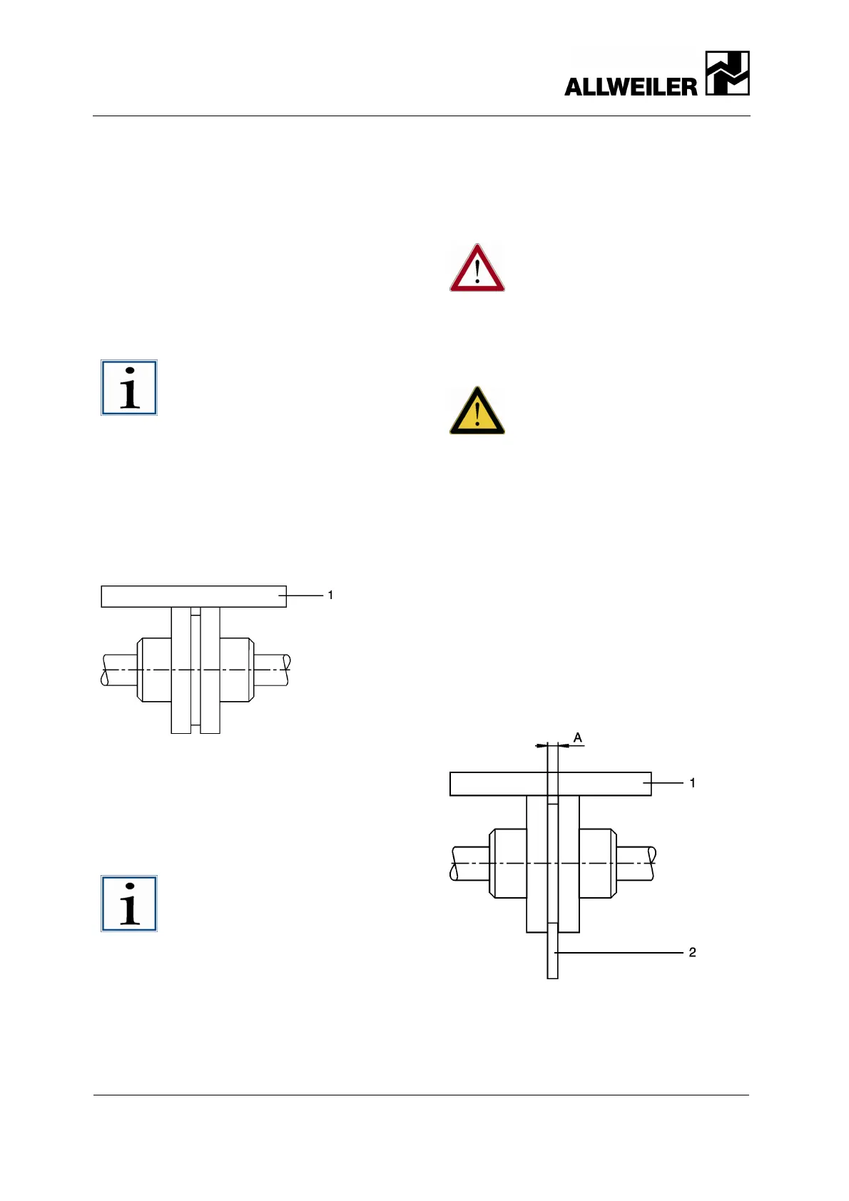
Fig. 4 Check for twisting
• Measure at the circumference of the
coupling at two levels, offset by 90°.
• Use the straightedge (1) to check the
light gap at the outer diameter:
Lay the straightedge over both halves
of the coupling.
Notice!
Couplings with a spacer piece
(spacer coupling) can also be
checked with a caliper.
• Loosen fastening screws at the foot of
the discharge casing (504) ( see
sectional drawings on pages 43, 44,
45, 46, 47, 48, and 49). After loosening
of the screws, the foot of the discharge
casing may not be tilted, nor spring,
nor be under pressure.
• If major deviations are found, loosen
the base plate attachment and remove
the tension by refilling.
6.4 Coupling
Fine adjustment of the coupling:
Danger!
Life-threatening danger from
moving parts!
► Shut off the motor's power
supply and lock it in the off
position before all assembly
and maintenance tasks.
Improper alignment of the coupling
will cause property damage!
► In the case of height, lateral,
or angular misalignment, align
the drive precisely with the
pump.
► For detailed information and
for special couplings: (
Manufacturer’s specifications).
Checking alignment of the coupling
Aids, tools, material:
• Feeler gauge
• Straightedge
• Caliper (option if coupling has spacer
piece)
• Other suitable tools, such as a laser
alignment device
Fig. 5 Check coupling alignment
1. Measure at the circumference of the
coupling at two levels, offset by 90°.
2. Use the straightedge (1) to check the
light gap at the outer diameter:
 Loading...


