5000KIT | 5000KIT AUTOMATION SET80
CONTROL UNIT
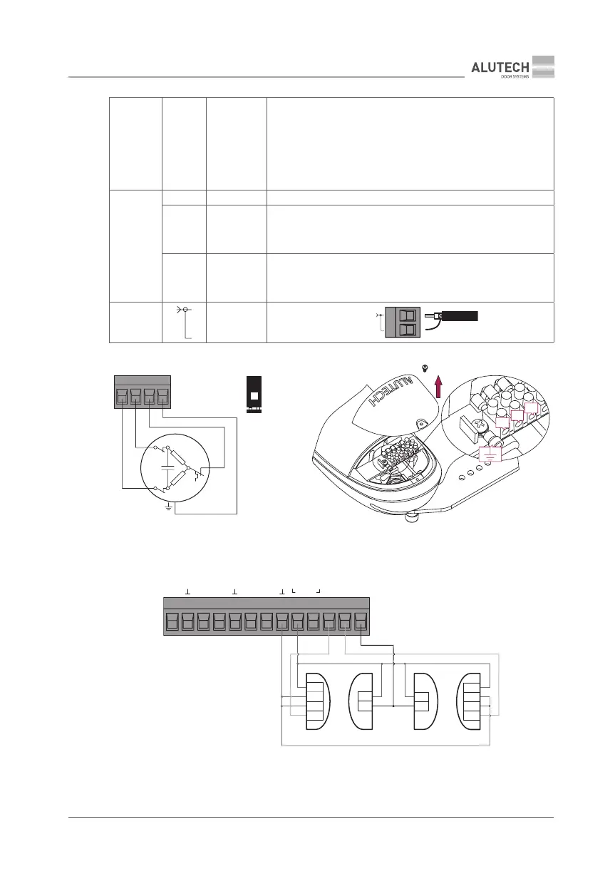
X13 PH.T —
Output for automatic testing (Phototest) of the devices connected to
the PH1 and / or PH2 inputs.
Fig. 20—connecting photocells for initiating a Phototest; for details
about enabling the output, see section 7 ‘Setting up operating
parameters’.
When the power supply to a photocell receiver is disconnected
for a short period and then connected again, an automatic test is run
to check the operation of the photocells prior to the motion start
X10
Lc — COM contact for the connection diagram of the electric lock
NO —
Normally open (NO) relay contact for the connection of the electric
lock—see diagram (g. 21).
Contact load not exceeding 5A 250VAC / 28VDC. For details about
enabling the output, see section 7 ‘Setting up operating parameters’.
NC —
Normally closed (NC) contact for the connection of the electromagnetic
lock—see diagram (g. 22).
Contact load not exceeding 5 А 250VAC / 28VDC. For details about
enabling the output, see section 7 ‘Setting up operating parameters’
X9
—
External radio antenna
RG58
M
~
L1
L2
N
X2
X3
XN1
XN 2
N
L
1
L
2
Figure 19. Connecting -5000 drive to the module.
Module crossovers XN1 and XN2 should be installed (with contacts closed)!
OP CL SBS
SPED
PH1PH2
PH.T
+24V
NC
+
-
TX1RX1
+
-
GND
NC
+
-
TX2RX2
+
-
GND
X13
Figure 20. Connecting safety devices (photocells) for automatic testing of their operation (Phototest)
TX1 and RX1—transmitter and receiver for safe closing photocells;
TX2 and RX2—transmitter and receiver for safe opening photocells