M19-2101 REVISION 2.0 DVNEXT RHEOMETER - OPERATIONAL MANUAL
3.5 Attaching a spindle to the magnetic coupling
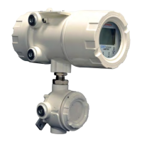
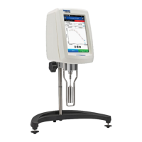
Align two opposing spindle slots (see Figure 3-6) with the two pins inside the coupling (see Figure 3-7).
Figure 3-6 Figure 3-7
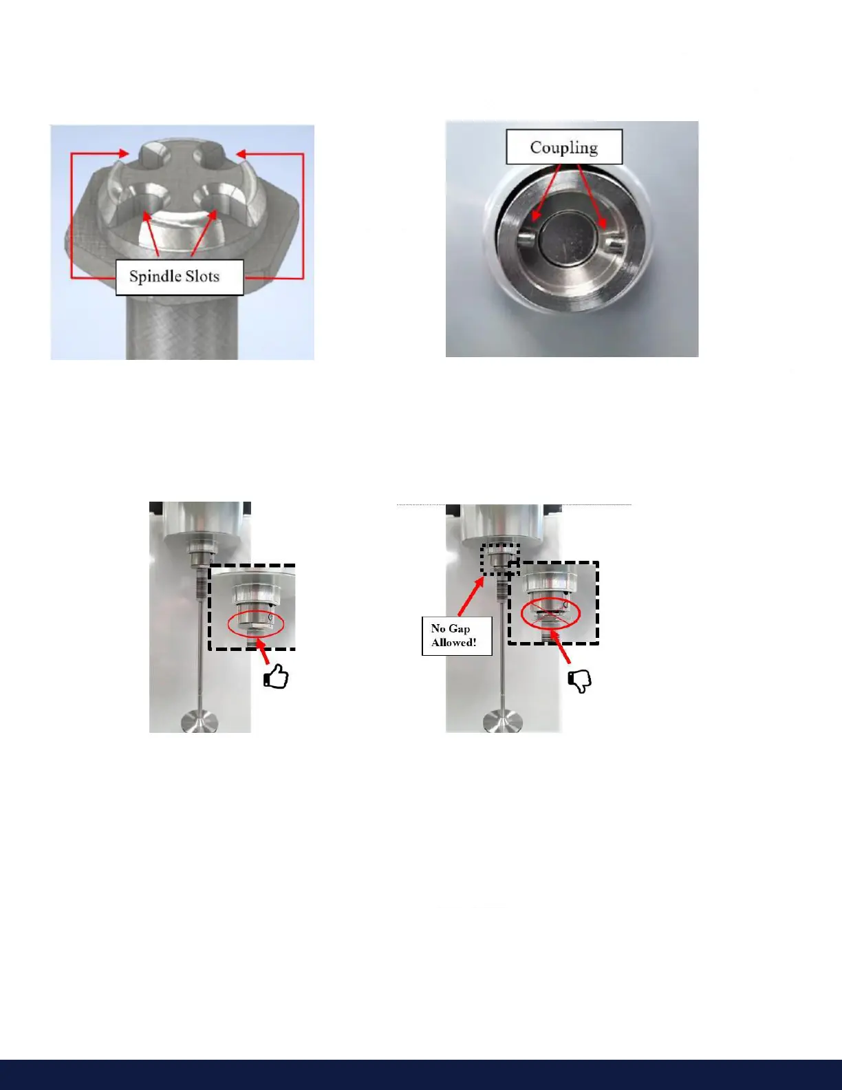
Carefully insert the spindle into the coupling so the slots are fully engaged with the pins. You should feel the pull of
the magnet as the spindle seats in the coupling.
When properly aligned, there should be no gap between the spindle and the coupling (see Figures 3-8 and 3-9).
Figure 3-8: No Gap, Correct Figure 3-9: Gap, Not Correct
3.6 Removing a spindle from the magnetic coupling
• With the motor turned OFF, carefully grasp the spindle shaft (see Figure 2I-10). and pivot it sideways to
separate it from the magnetic coupling (see Figure 2I-11). DO NOT PULL DOWN ON THE SPINDLE!!
• Gently lift the Spindle just enough to minimize any pressure on the pivot point and jewel inside the DVNext.
• While still lifting, gently push the Spindle to the side like a pendulum to disengage it from the magnetic
coupling. The spindle and coupling should separate easily. If they do not separate easily, DO NOT FORCE
IT. Stop and try pushing it in a dierent direction.
• Continue pushing the spindle in an unrestrictive direction until it is completely detached from the magnetic
coupling.
 Loading...