Installation and Start-Up | 3-15
Weatherproof wall/z-purge option
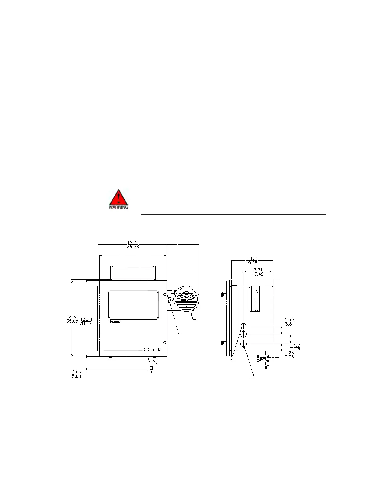
Figure 3-12 shows the wall- and pole-mounting dimensions for the Series
2000 weatherproof Z-purge enclosure. To mount this control unit version,
you must also connect instrument air to the Purge Inlet and set the pres-
sure and flow as indicated on the warning tag on the control unit.
Z-Purge shutdown procedure
Disconnect power to the control unit for one hour while maintaining
purge air flow before the door is opened, unless the area is demonstrated
to be nonhazardous.
Z-Purge start-up procedure
Power should not be restored after the enclosure has been opened until
the enclosure has been purged for one hour at a pressure of 0.4” of water.
Don’t open the Z-Purge enclosure until you have verified that the
area has been classified as nonhazardous.
Pressure
Gauge
1/2” Conduit
Entry (2.22 cm)
Two 3/4” Conduit
Entries (2.70 cm)
Purge Air Inlet
1/8” Compression Fitting
Metering Valve
Exhaust
Restriction
7.50
19.05
5.31
13.49
12.00
30.48
Flange
8.00
20.32
5.88
14.94
Figure 3-12.
Series 2000, weatherproof
wall/z-purge.
 Loading...