Appendix D – Cable Details and Pinout Info
129
Instruction Manual – DXLink™ Twisted Pair Transmitters/Receiver
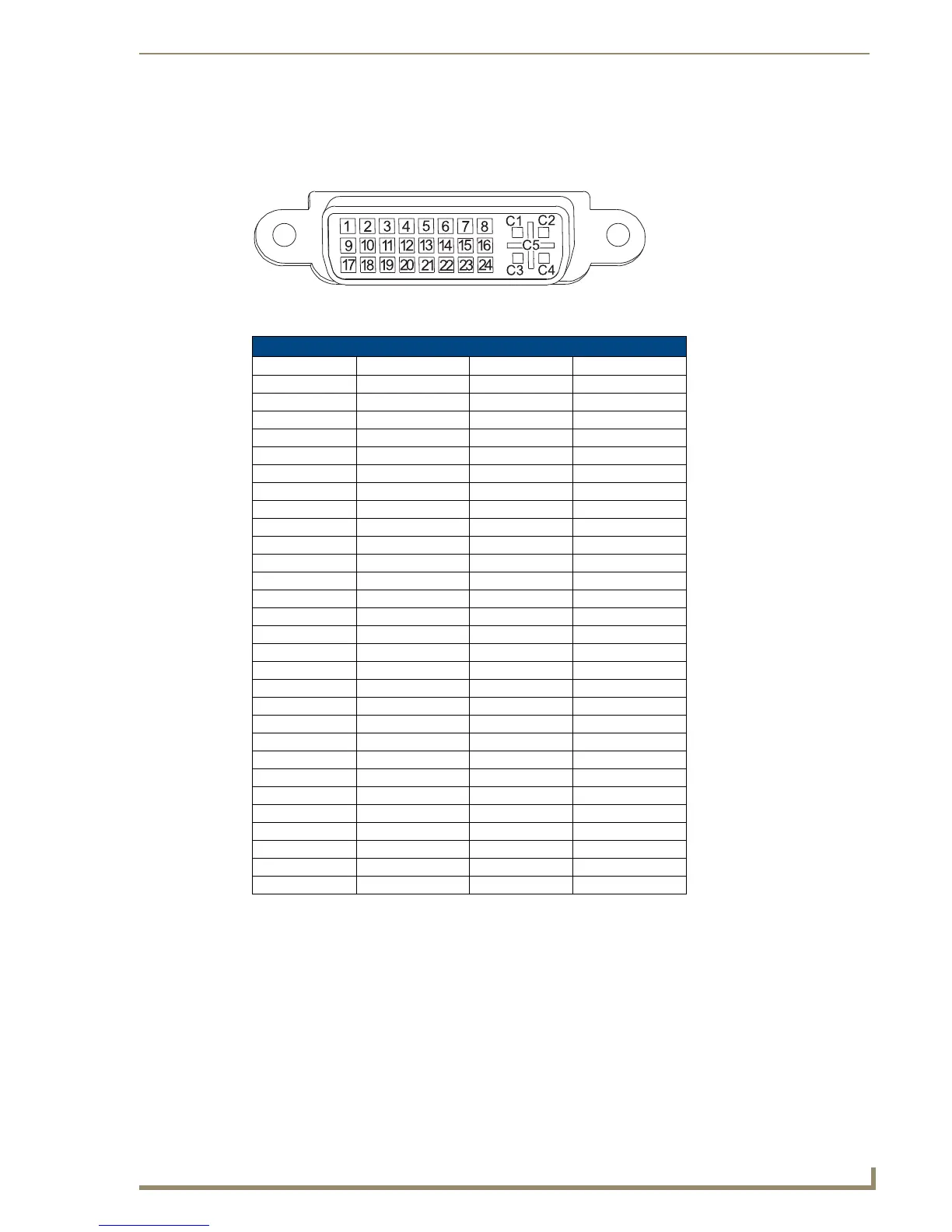
DVI Pinout for DVI-to-HDMI Cable Adapter
The pinout in FIG. 43 is for DVI-to-HDMI cable adapters which can be used with the modules when a
DVI-I signal is required
.
*The +5 VDC on output pin 14 supplies a maximum of 55 mA.
FIG. 43 DVI pinout for DVI-to-HDMI cable adapter
DVI Connector Pinout
DVI Input Pin # Signal Name DVI Output Pin Signal Name
1 Data 2- 1 Data 2-
2 Data 2+ 2 Data 2+
3 Gnd 3 Gnd
4 n/c 4 n/c
5 n/c 5 n/c
6 DDC-CLK 6 DDC-CLK
7 DDC-Data 7 DDC-Data
8 n/c 8 n/c
9 Data 1- 9 Data 1-
10 Data 1+ 10 Data 1+
11 Gnd 11 Gnd
12 n/c 12 n/c
13 n/c 13 n/c
14 +5 VDC in 14 +5 VDC out*
15 Gnd 15 Gnd
16 Hot-Detect 16 Hot-Detect
17 Data 0- 17 Data 0-
18 Data 0+ 18 Data 0+
19 Gnd 19 Gnd
20 n/c 20 n/c
21 n/c 21 n/c
22 Gnd 22 Gnd
23 CLK+ 23 CLK+
24 CLK- 24 CLK-
C1 n/c C1 n/c
C2 n/c C2 n/c
C3 n/c C3 n/c
C4 n/c C4 n/c
C5 n/c C5 n/c