36 Operator's Manual – Self-loading Bale Carrier TSR-3450 Anderson Group
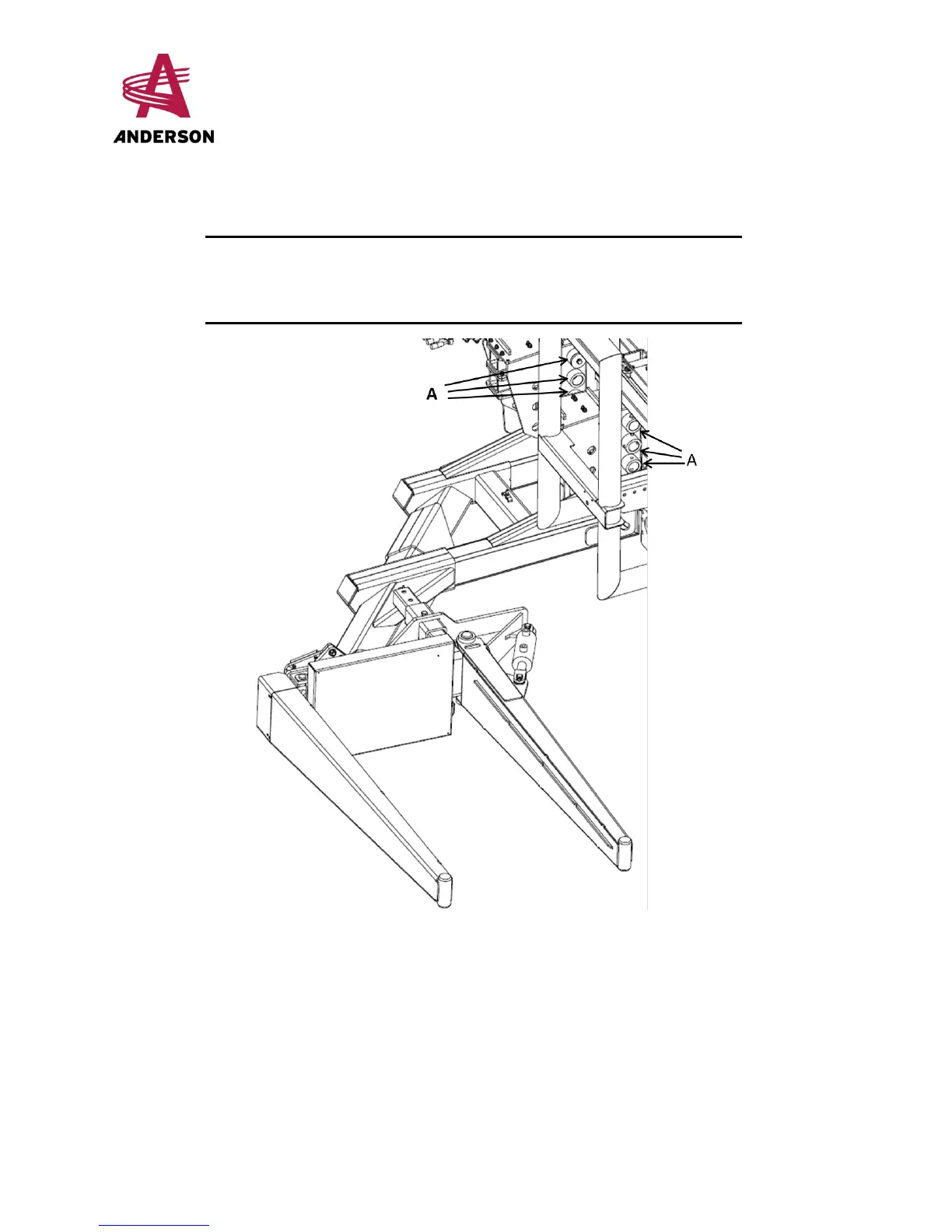
4. With your lifting device, lift the loading arm up to the desired height such that the holes for
each arm post are aligned with the attachment holes (A in Figure 13 – Loading Arm Position)
in the base-frames.
NOTE: There is no set rule for adjusting the arm position. The
operator must determine what adjustment is best
suited for the height of the bales being loaded.
Figure 13– Loading Arm Position
5. Re-insert the pins in the base-frame holes and in the arm posts, and then replace the bolts
and washers.
6. Adjust the cylinder height by aligning its base (B) with the appropriate holes (C) (see Figure
14 – Cylinder Base Height Adjustment).
7. Re-insert the pin, and then replace the screw.
 Loading...