Installation and Layout
3-10 Infinity Smoke Control Guide
TOC
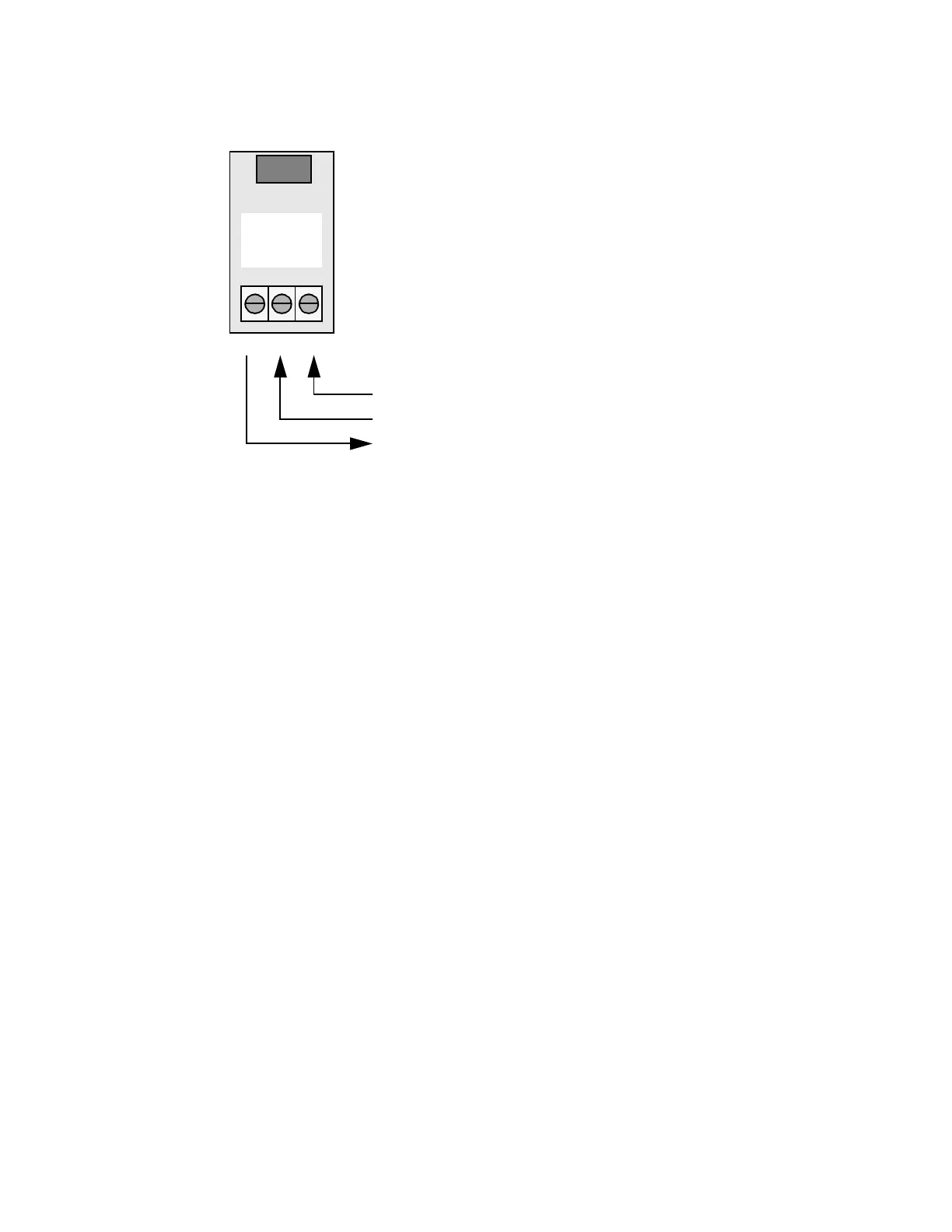
Figure 3-5. RS-232 Terminal Block
Zoned Alarm Contact Wiring (Optional)
As stated in the previous chapter, if you are not using a Fire Panel that
is part of the Andover Controls Listing, you will have to connect the Fire
Panel to the smoke control system using the Zoned Wiring method. This
involves connecting a set of wires for each zone from the Fire Panel to
the FSCS. Each contact closure output on the Fire Panel will be wired to
an input on the FSCS, which is read by the CX9200. These FSCS inputs
will be wired at a terminal block in the FSCS (not shown). This wiring
must be less than 20 feet in length, and must be enclosed in conduit.
The Q-Card Processor PCB
The Q-Card controls the RS-232 communications with the CX9200,
reads the FSCS switch inputs from the 80 Point Switch Input cards, and
controls which Status Indicators will be turned on by the 80 Point LED
Driver cards.
The Q-Card has a Reset switch and an Options dipswitch. Pressing the
Reset switch resets the processor, but maintains the current status of the
LEDs. The Options dipswitch is used to set the RS-232 baud rate and to
enable the auto-blanking feature. When the auto-blanking feature is on,
the status LEDs will be cleared if the FSCS does not receive any data
from the CX9200 within 10 seconds. The Q-Card only reads the Options
dipswitch after a Reset.
COMMON
DATA IN
DATA OUT
RS-232
PROTECTION
PCB
OUT IN COM
Wire to pin 7 on the CX9200 RS-232 port
Wire to pin 2 on the CX9200 RS-232 port
Wire to pin 3 on the CX9200 RS-232 port
Technical Manuals Online! - http://www.tech-man.com