Chapter 3 — Performance Verification 3-7 50 MHz Calibrator Power Level (All Models)
ML248xx, ML249xA MM PN: 13000-00164 Rev. K 3-9
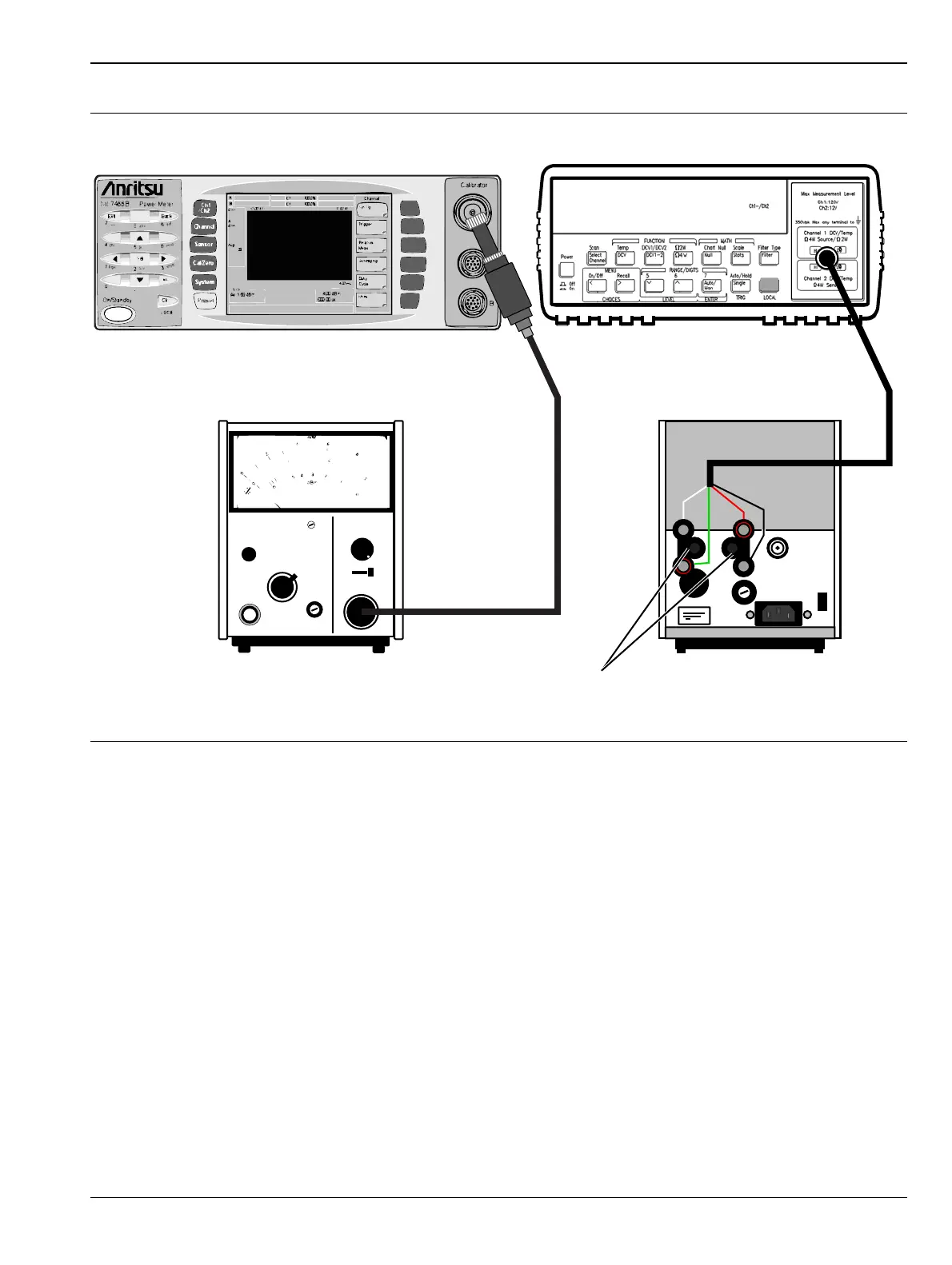
4. Connect the Agilent Power Sensor 8478B to the Agilent 432A Power Meter.
5. Power on the 432A power meter and the 34420A voltmeter. Allow the units to warm up for 15 minutes
before taking any measurements.
6. On the front panel of the 432A power meter, set the Mount Resistance to 200 ohms as shown in
Figure 3-4.
7. On the front panel of the 432A power meter, set the Calibration Factor to 100.
8. After the 432A and 34420A have warmed up for 15 minutes, perform a zeroing of the 432A power meter
according to the instructions listed in the 432A user manual.
9. On the front panel of the 432A power meter, set the Range to 0 dBm.
10. On the ML248xx or ML249xA, verify the RF Calibrator is off.
11. Connect the 8478B power sensor directly to the ML248xx or ML249xA calibrator.
Figure 3-3. Equipment Connection for Calibrator Power Level Verification
432 A POWER METER
FINE ZERO
mW - RANGE - dBm
CALIBRATION FACTOR
MOUNT RESISTANCE
200
0
-5
5
100
100
Shift
ML248xx or ML249xA Agilent 34420A Nano Volt Meter
Agilent 432A
Power Meter (Rear)
Agilent 8487B
Power Sensor
BNC to
Binding Post
Adaptors
Agilent 432A
Power Meter (Front)
115
 Loading...


