3-2 Measurement Setup Chapter 3 — Quick Start Guide
3-2 PN: 10580-00175 Rev. N MS272xB + MS8911B UG
3-2 Measurement Setup
Connecting the Input Source
Connect the input signal or antenna to the appropriate test connector on the top of the
instrument. For connector descriptions, refer to Figure 2-10 on page 2-13.
Editing and Entering Values
• Parameter values that are ready for editing are displayed in red on the submenu key.
After changing the value, press Enter to set the new value.
• Some submenu keys have toggled parameter values (On / Off, Low / High). On these
submenu keys, the current value is underlined. Press the submenu key to toggle the
value.
• Use the arrow keys, numeric keypad, or rotary knob to change submenu key values,
to select list box options, or to enter filenames.
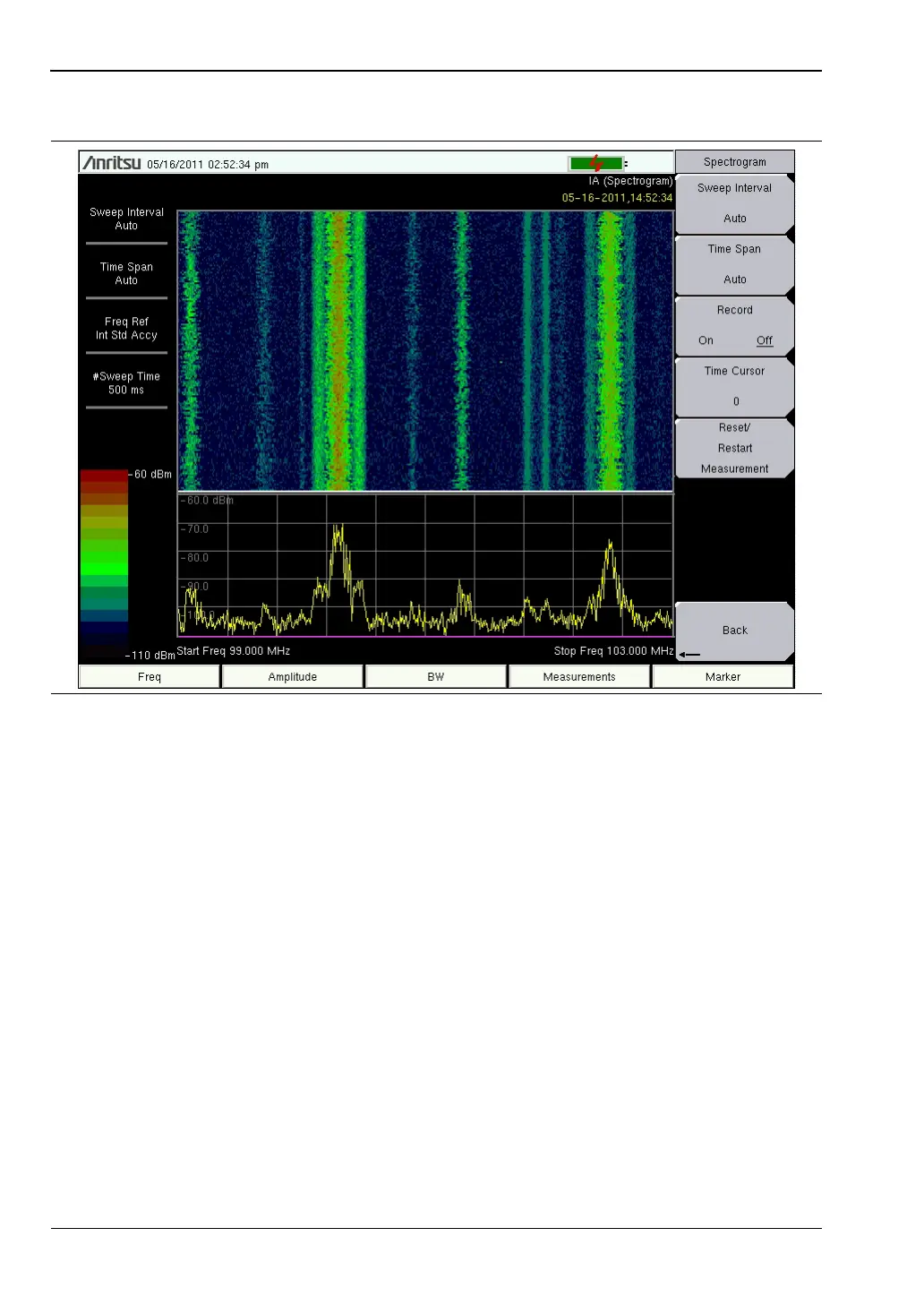
Figure 3-1. Spectrogram Example