Chapter 5 — Assembly Replacement 5-3 Spectrum Analyzer Module Assembly Replacement
MS272xC MM PN: 10580-00279 Rev. E 5-5
5-3 Spectrum Analyzer Module Assembly Replacement
This procedure provides instructions for removing and replacing the Spectrum Analyzer PCB Assembly.
The Spectrum Analyzer Module Assembly is located in the back half of the case and includes the Top
Connector Panel.
1. Open the case as described in Section 5-2 “Opening the Spectrum Master Case”.
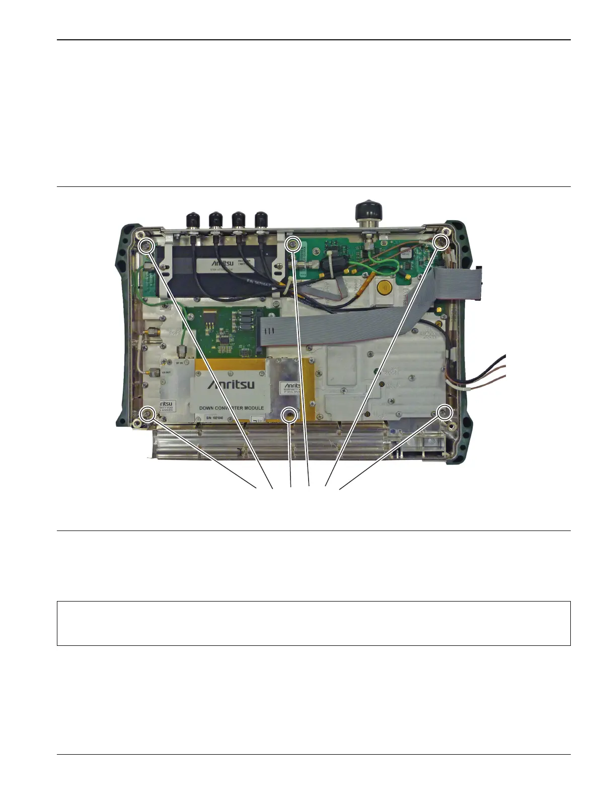
2. Use a Phillips screwdriver to remove the six screws securing the Spectrum Analyzer Module Assembly to
the back half of the instrument case (Figure 5-5).
3. Carefully lift up and remove the Spectrum Analyzer PCB Assembly and attached Top Connector Panel.
4. Reverse the above steps to install the new Spectrum Analyzer PCB Assembly.
Figure 5-5. Spectrum Analyzer PCB Assembly
Note
There is an RF gasket material between the two halves of the case, and in the connector panel
grooves. Take care not to remove or damage this material when removing or replacing the
Spectrum Analyzer Module and connector panel assembly.