5-4 Main PCB Assembly Replacement Chapter 5 — Assembly Replacement
5-6 PN: 10580-00279 Rev. E MS272xC MM
5-4 Main PCB Assembly Replacement
This procedure provides instructions for replacing the Main PCB assembly. The Main PCB assembly is located
in the front panel half of the instrument.
1. Open the case as described in Section 5-2 “Opening the Spectrum Master Case”.
2. For Main PCB Assembly replacement of units with Option 31. Remove the two screws holding the
GPS PCB to the Main PCB Assembly. Straighten the bend tab in the upper-left corner of the PCB and
remove the GPS PCB board and cable from the Main PCB. Reattach the GPS PCB and reroute the cable
on the replacement Main PCB Assembly.
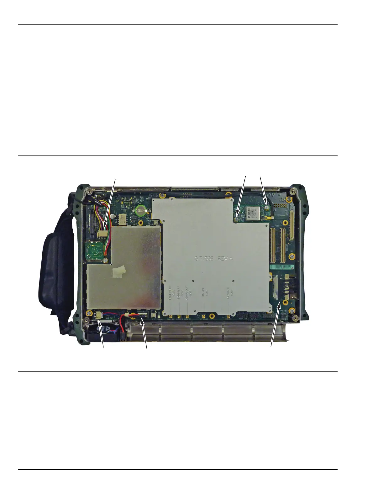
3. Disconnect the Fan connector on the Main PCB Assembly (Figure 5-6).
4. Disconnect the Encoder Knob connector on the Main PCB Assembly.
5. Disconnect the Battery connector on the Main PCB Assembly.
6. Disconnect the LCD connector on the Main PCB Assembly.
Figure 5-6. Disconnect the Cable Connectors on the Main PCB Assembly
Option 31 PCB
Remove 2 Screws
Disconnect Encoder
Disconnect
Fan
Disconnect
Battery
Disconnect
LCD