Chapter 2 — Spectrum Analyzer Verification 2-7 Spectrum Analyzer Absolute Amplitude Accuracy
MS272xC MM PN: 10580-00279 Rev. E 2-15
6. Set the power meter to display both Channel A and Channel B. Press the Sensor key, the Cal Factor
submenu key, and then the Freq submenu key. Use the keypad to enter the value matching the
frequency of MG3692x or MG3695C as the input signal frequency, which sets the power meter to the
proper power sensor calibration factor. Repeat for Channel B. Press the System key to display the power
reading.
7. Adjust the power level of the MG3692x or MG3695C to get a reading on Sensor A that matches the test
power level in the first column of Table A-9, “Characterization Chart for 50 MHz Amplitude Accuracy
Verification” on page A-5.
8. Record the Sensor B reading in the “Required Sensor B Reading” column of Table A-9.
9. Repeat Step 7 and Step 8 for the other power levels in the first column of Table A-9, and record the
Sensor B readings in the second column.
Measuring the Unit for 50 MHz Amplitude Accuracy
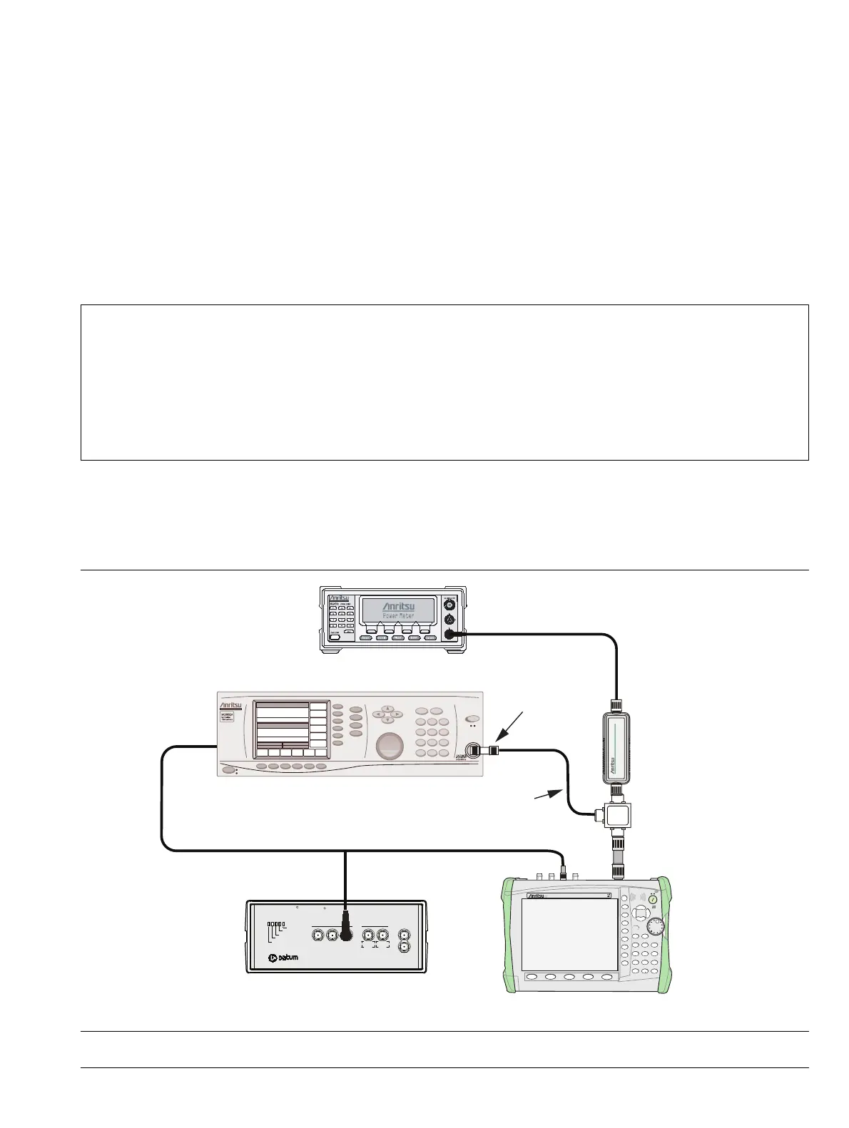
1. Connect the equipment as shown in Figure 2-4, disconnecting Sensor A from the Attenuator, and
connecting the RF In port of the MS272xC to the splitter output via the Attenuator.
Note
Before continuing, allow a 30 minute warm-up period for the internal circuitry to stabilize.
The listed Amplitude Accuracy specifications in Appendix A apply when the instrument is being
verified in an environment between 20°C and 30°C after a 30 minute warm-up period. For an
instrument that is not being verified in a temperature controlled environment, but within a
temperature range between –10°C and 50°C (–10°C and 40°C for MS2726C only) and after a
60 minute warm-up, add ± 1 dB to the Amplitude Accuracy specification for frequencies from
100 kHz to 32 GHz, or add ± 2 dB to the Amplitude Accuracy specification for frequencies from
32 GHz to 40 GHz.
Figure 2-4. 50 MHz Amplitude Accuracy Verification, Test Setup
10 MHz Reference
Oscillator Warmup
Oscillator Ready
Failure
1 PPS Sync
1 PPS OUT
1 MHz 5 MHz 10 MH
5 MHz 10 MHz
Sine wave Out AUX
1 PPS IN
Power
TESTIME
PLUS
R
RubiSource T&M
R
10 MHz
Sine Out
0
1
Preset
4
Measure
7
File
2
Calibrate
5
Trace
8
System
3
Sweep
6
Limit
9
Mode
Shift
Enter
Back
On
+/-
Off
ESC
Fault
MS2722C
Spectrum Analyzer
MS272xC Spectrum Master
SpectrumMaster
Ext Ref In
MG3692x Signal General
ML2438A Power Meter
Sensor B
1870A
Power Splitter
10 dB
Attenuator
Adapter
15NNF50-1.5B
Ext Ref In
(back panel)