Do you have a question about the Areva FLUOKIT M24+ and is the answer not in the manual?
Details AREVA's service unit offerings and expertise for clients.
Describes AREVA's training programs and expertise for electrical equipment.
Explains the eco-design principles and material revalorisation in product manufacturing.
Outlines the responsibilities of the user regarding product installation and operation.
Provides essential reminders on normal operating and environmental service conditions for the equipment.
Gives specific safety instructions for operations and interventions on energized electrical equipment.
Lists other relevant technical notices and documentation for consultation.
Lists the necessary tools and products that are not supplied with the equipment.
Explains the symbols and conventions used throughout the user manual for clarity.
Specifies the correct tightening torque values for standard nut and bolt assemblies.
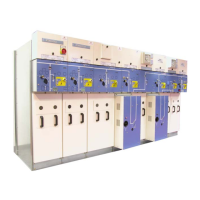
Provides a general description of the FLUOKIT M24+ Functional Units and their compliance with standards.
Details the physical dimensions and approximate weights of various Functional Units.
Illustrates and describes the components and layout of different Functional Units.
Defines the conditions and methods for transport and delivery of the equipment.
Describes the specific packaging methods for road, rail, air, and maritime transport.
Lists the contents of the accessories package required for installation and connection.
Provides guidelines for receiving and accepting the delivered equipment and checking its condition.
Indicates the locations of technical data plates on the equipment for identification.
Details the correct procedures for handling the Functional Units during transport and installation.
Specifies the recommended environmental and physical conditions for storing the equipment.
Defines the different levels of intervention and the personnel qualified to perform them.
Describes the requirements for the civil engineering structure needed for switchboard installation.
Provides instructions on how to safely unpack the Functional Units at the installation site.
Guides the user on the proper methods for handling the Functional Unit during installation.
Refers to the civil engineering guide for switchboard installation requirements.
Gives advice on the sequence and placement of Functional Units during switchboard assembly.
Details the step-by-step process for installing individual Functional Units.
Explains the specific installation requirements for units with internal arc protection.
Describes the methods for securely anchoring the Functional Units to the floor.
Guides on connecting the grounding circuit between different Functional Units.
Explains how to establish the main earthing connection for the switchboard.
Provides instructions and precautions for making standard connections to the busbars.
Details the procedure for connecting a 1250 A busbar, including mounting and tightening.
Explains how to connect busbars of different current ratings (630 A and 1250 A).
Outlines the process for connecting a 1250 A busbar to PBB or PGC isolating switches.
Describes the procedure for coupling two Fluokit M24+ functional units together.
Details the preliminary steps and checks for preparing HV cable connections.
Provides essential instructions and safety warnings for connecting HV cables.
Guides on preparing the HV cables, including cutting grommets and fitting them.
Explains the connection procedure for IS Functional Units using round or rectangular lugs.
Details the connection process for PF or PFA Functional Units, similar to IS units.
Covers securing cables and connecting their screen braids for electrical safety.
Guides on connecting cables in units with current transformers, including positioning lugs.
Illustrates the connection point for earthing the HV cable screen braids.
Provides a step-by-step guide for correctly fitting fuses into PF-PFA Functional Units.
Explains the function and type of sensors used for fault detection and signalling.
Details the correct positioning and mounting of fault detection rings on cables.
Offers final instructions and checks after completing cable connections.
Describes how to identify and mark functional units on the Low Voltage box cover.
Explains the motorized remote control interface for switches, including its components.
Details the connection procedure for metering low voltage wiring to the PGB Functional Unit.
Outlines the connection process for metering low voltage wiring to the TM Functional Unit.
Explains the pin foolproofing mechanism for the remote control connector in public distribution systems.
Identifies and describes the function of each pin on the remote control connectors.
Guides on mounting and connecting rings, including cable routing and earthing.
Provides instructions for commissioning the double shunt layout, including battery checks.
Explains the principle of automatic load transfer between normal and backup power sources.
Presents the components and operation of the normal/backup function, including the selector switch.
Details the mechanical interlocking system that prevents parallel connection of power sources.
Recalls the state of the delivered Functional Unit and accessory storage.
Describes the optional wall storage rack for fuses and levers.
Refers to manual for operation of units with C410-C410S-C410M controls.
Refers to manual for operation of units with C430-C430M controls.
Refers to manual for operation of units with C440-C440M controls.
Details the procedure for performing cable tests before commissioning and during regular checks.
Guides on installing the removable earthing switch device and related checks.
Explains the operating manoeuvres specific to the TM Functional Unit.
Details the steps for opening both upstream and downstream earthing switches.
Provides instructions on how to close the load break switch.
Explains the procedure for closing the circuit breaker, including locking and unlocking.
Outlines the steps for de-energizing the PGB Functional Unit in reverse order.
Details the procedure for opening the downstream earthing switch.
Guides on how to open the upstream earthing switch.
Explains the steps to close the load break switch.
Details the procedure for closing the circuit breaker.
Outlines the process for de-energizing the PGC Functional Unit.
Explains the functional mechanical interlocks designed to prevent operating errors.
Describes how to lock out equipment using padlocks, including safety precautions.
Guides on performing locking operations using key locks and consulting relevant manuals.
Recalls pre-shipping tests and storage recommendations for optimal commissioning.
Instructs on recovering, verifying, and tidying away tools and accessories after work.
Lists essential pre-commissioning information, including safety regulations and serial number recording.
Details final visual, mechanical, and electrical checks required before commissioning.
Explains the procedure for energizing the "Incoming" Functional Unit and busbar.
Guides on energizing a second incoming unit from the same power source.
Details how to check phase balance using a VPIS indicator and its connection.
Outlines the final steps for energizing the entire switchboard.
Defines the different levels of maintenance and the qualifications required for each.
Refers to specific manuals for preventive maintenance of mechanical control mechanisms.
Provides a table of preventive maintenance operations recommended for functional units.
Details procedures for checking HV connections, including torque verification and visual inspection.
Explains when and how to grease contact surfaces for optimal performance and longevity.
Outlines corrective maintenance actions, including replacements and modifications.
Provides step-by-step instructions for replacing HV fuses, including safety measures.
Details the process for replacing the Voltage Detection System (VDS) components.
Lists common anomalies, their probable causes, and recommended remedies for troubleshooting.
Defines what constitutes a spare part and the requirements for its replacement.
Explains the importance of equipment identification for ordering spare parts.
Specifies the recommended storage conditions for components to maintain their integrity.
Identifies products designated as consumables necessary for maintenance.
Discusses the valorisation process and material composition for end-of-life equipment.
Provides crucial safety instructions to be followed during dismantling and decommissioning.
Guides on the process of dismantling equipment services and sorting materials for recycling.
Offers specific recommendations for handling SF6 gas circuit breakers during end-of-life processes.
Details the distribution and valorisation of materials used in PGB units.
| Rated Voltage | 24 kV |
|---|---|
| Rated Short-Circuit Breaking Current | 25 kA |
| Insulation Medium | SF6 |
| Type | Gas-insulated switchgear |
| Model | FLUOKIT M24+ |
| Application | Medium voltage distribution |
| Compliance | IEC 62271-200 |
| Rated Current | 1250 A |