14
F Four fixed slinging points are
provided for on the roof of each
Functional Unit.
These lifting lugs
are to be removed when
the Functional Units are in the
immediate proximity of their
definitive installation.
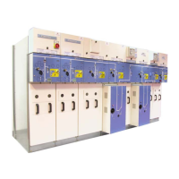
F Lift the Functional Unit by
4 slings each one capable of
supporting 1,000 kg.
F Respect the minimum carrying
height as shown on the above
diagram.
1 m min.
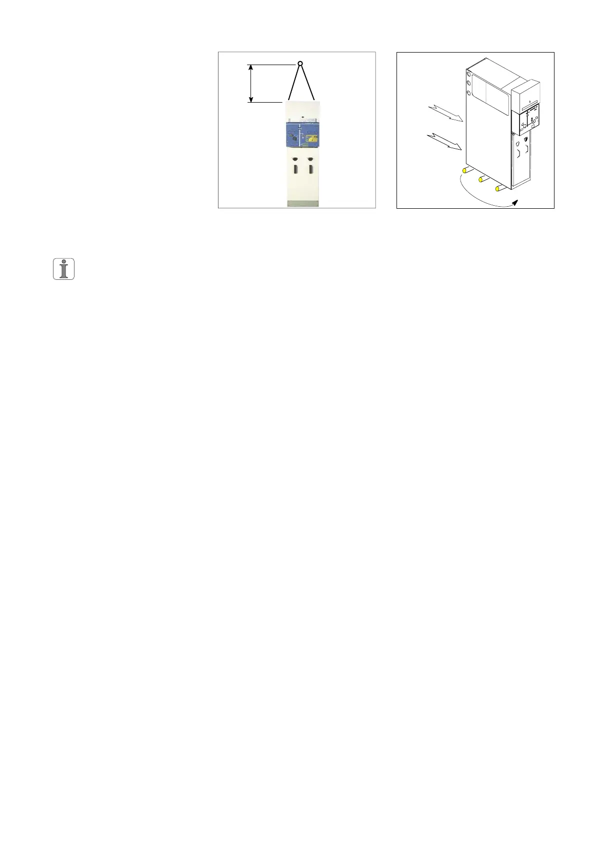
F Slide the Functional Unit along,
using three cylindrical rollers of
30 mm min. diameter.
F Thus moving it to its final
installation place.
5.4 Installation of a switchboard
Please refer to the instructions in
the Civil Engineering Guide
(See § 2.5).
The limits of the civil engineering
layout depends on the type and
quantity of materials to be installed.
Position the cells whilst respecting
minimum clearance distances in
front of, behind and to each side of
the switchboard.
5.5 Installing Functional Units
For a switchboard composed of 1
to 8 Functional Units, it is advisable
to begin installing the equipment on
the side of the room opposite the
entrance.
For switchboards using more than
8 units, start by installing the equip-
ment to the middle of the switch-
board.
5.6 Revalorizing packaging waste
After unpacking, the materials
remaining (cover, wooden floor
panel, etc) should be sorted and
sent to the appropriate recycling
services.