30
9.2 Identification and function of the pins [Public Distribution]
Pin N° Remote Control Function (RC) Pin N° Remote Control Function (RC)
1 − 48V
6 + 48V
2 HVA closing command 7 Command neutralised
3 HVA opening command 8 Presence/absence of HVA voltage
4 HVA switch open 9 Reserved
5 HVA switch closed 10 Reserved
A neutralization switch is located
on the front face, on the box for
each Functional Unit.
It is padlockable in the open
position and ensures the
sectionalizing of the auxiliary
power supply (+ 48 V, − 48 V).
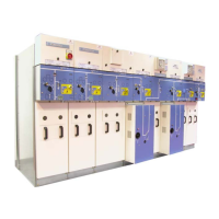
F Neutralization switch. F Passing from UFA type to UFB type:
recover the labels supplied in the bag
attached to the LV link.
Operations to be carried out
1 − Beside the neutralizing switch,
attach the UFB Double Shunt label
above the other one.
2 − Modify the connector’s fool-
proofing device (see § 9.1).
3 − On the connector itself, attach
the UFB label above the one
marked UFA.
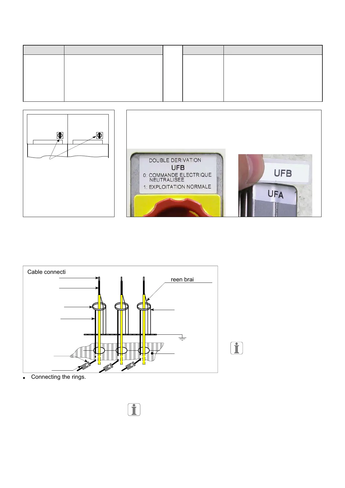
9.3 Mounting and connection of the rings
male
ËËËËËËËËËËËË
ËËËËËËËËËËËË
ËËËËËËËËËËËË
F Connecting the rings.
Cable connection lug
Cable earthing
screen braid
Ring
Secondary
for the rings
female
Earthing the
rings
HV cable
Floor panel for the
Functional Unit
Connectors
F Mount the rings which are
inside the Functional Unit.
F Lower the LV cable for each
ring (equipped with a female
connector) through the floor
panel, via the HV cable trough.
F Below the floor panel, connect
each female connector to the
male connector on the cable
bundle coming from the
automatic changeover switch.
The screen braids for the
cables absolutely must pass
through each ring, in the
reverse direction to the HV cable,
before being connected to earth.
9.4 Commissioning the double shunt layout
Ensure that the batteries are pro-
perly charged before the commis-
sioning tests
Carry out replacement of
these batteries every 4 years.
Apply the commissioning instruc-
tions in chapter 16.