31
10 Normal/Backup function
10.1 Principle
This function provides an automatic
transfer of the load from the "Nor-
mal" source to a "Backup" source in
the event of a loss in voltage from
the former. It will automatically
return to the "Normal" source once
the voltage has been definitively
restored.
Between the 2 Functional Units cal-
led Cable 1 and Cable 2, the selec-
tion of the "Normal" source is made
by a selector switch.
A mechanical function interlock pre-
vents the 2 sources from being
connected in parallel.
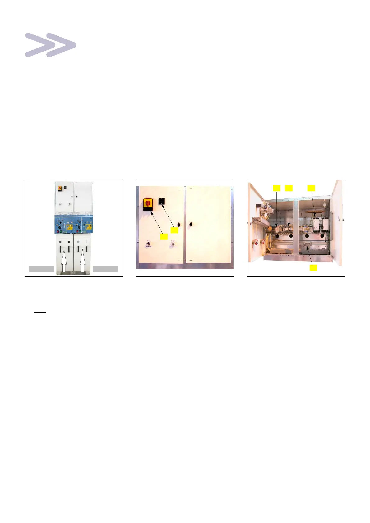
10.2 Presentation
F IS Functional Units are coupled
together and equipped with
C440M mechanical control
mechanisms.
N.B.: Shown without the
electrical energy unit.
Câble 1 Câble 2
F Front face of the LV box.
1. "Normal" source selector
switch. It is padlockable in the 3
positions and must be set to 0
before any maintenance
operation.
2. Operations counter.
Increments a unit whenever the
Normal−Backup source carries
out a complete operating cycle.
When the operations counter is
located between 2 units, the
Normal−Backup operates on the
"Backup" source.
1
2
F The LV box groups together the
changeover automatic controls.
3. Protection fuses.
4. Automatic changeover
control relays.
5. RPT voltage detection relays.
6. Connections terminal block.
543
6