46
17.6 Corrective maintenance
C O R R E C T I V E M A I N T E N A N C E Levels
Replacements or modifications See chapter 1 2 3
Replacement of the three HV fuses 17.7 X X X
Replacement of the VDS (Voltage Detection System) 17.8 − X X
17.7 Replacement of the three HV fuses
Intervention Duration Busbar Cables Load Break Switch Earthing switch
Normal 30 mins. de−energized de−energized open closed
Possible 30 mins. energized de−energized open closed
Locking out the Functional Unit
All locking−out operations must be
performed according to the particular
rules for the network concerned.
Tools required:
− leather gloves
Parts required:
− 3 fuses with the same reference
(verify values in accordance with the
transformer power)
The body of a fuse can
become very hot following a
short circuit.
Take standard precautions (wear
work gloves).
For an apparently single
phase fault, it is imperative
that all 3 fuses be replaced.
F Open the load break switch.
F Ensure that there is an absence
of voltage.
F Close the earthing switch.
F Remove the cable access panel.
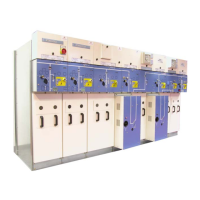
F Take hold of the fuse by the
upper part.
F Pull the fuse towards the front.
This causes the upper current
supply terminal shell to open.
The latter will remain open.
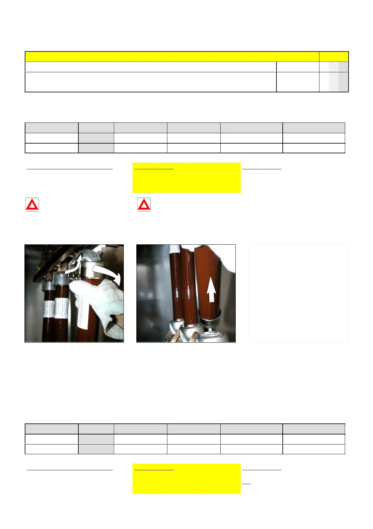
F Lift the fuse up to free it from
the lower current supply
terminal.
F Similarly remove all 3 fuses.
F Fit the replacement fuses by
carrying out the instructions
in § 7.9.
17.8 Replacement of the VDS (Voltage Detection System − LV capacitors)
Intervention Duration Busbar Cables Load Break Switch Earthing switch
Normal 30 mins. de−energized de−energized open closed
Possible 30 mins. energized de−energized open closed
Locking out the Functional Unit
All locking−out operations must be
performed according to the particular
rules for the network concerned.
Tools required:
− 10 mm open−ended spanner
Parts required:
− 1 VDS of the same reference
NB: The calibre of the VDS is depen-
dent on the voltage range.