13
5 Unpacking and installing the equipment
5.1 Type of Civil Engineering
The installation of a switchboard
requires a sufficiently flat and even
concrete structure. The dressing of
a top coat of cement using a rule
should eliminate any surface irregu-
larities greater than 2 mm per
metre.
A layout on iron supports for level-
ling off is ideal as they will also
serve as a guide for the adjustment
of the cement top coat.
The overall flatness of the support
surface should not show up any
deflection greater than 6 mm throu-
ghout the length of the switch-
board.
5.2 Unpacking the Functional Units
Proceed with unpacking the Functio-
nal Units only where they are to be
installed on site.
Tools required:
− Knife for road and rail
transport packaging
− Crowbar for air and sea
transport packaging
Use suitable protective gloves for
any handling operation.
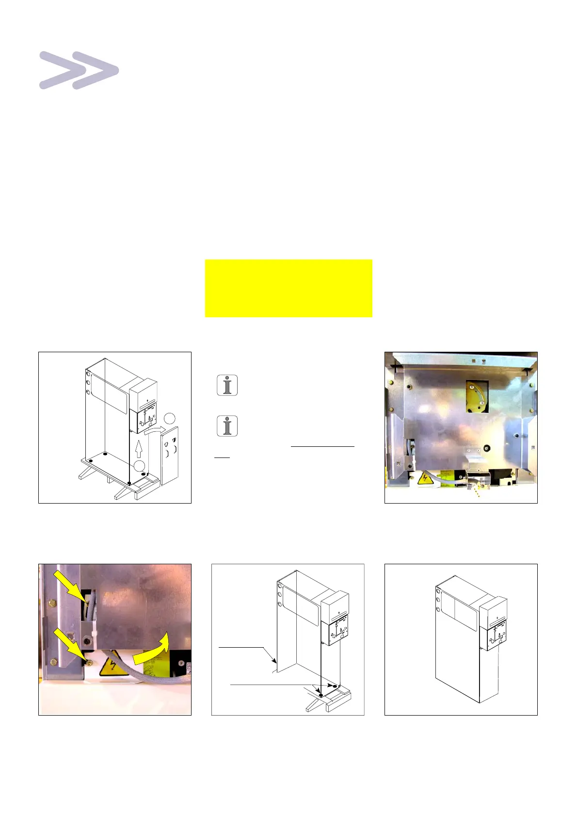
5.3 Handling the Functional Unit
F Remove the protective plastic
cover.
F Open the front panel:
1 − lift the panel
2 − pull the panel towards you.
1
2
F Special case of Functional Units
without an earthing switch.
Mark each panel in
accordance with the
corresponding Functional Unit.
For the PGB and PGC
Functional Units, remove
the wooden base without extrac-
ting the circuit breaker.
F Remove the mechanical control
hood (see the corresponding
manual § 2.5).
F Loosen the 2 CHC bolts.
F Pivot the lug towards the right.
F Remove the front panel.
F Remove the 4 fixing screws
(16 mm spanner) from the
wooden base.
F Free the Functional Unit.
2 rear fixings
2 front fixings
F Place the Functional Unit on the
ground.
F Replace the front panel