47
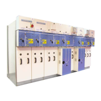
F The VDS is located in the
cross−brace which supports the
capacitive insulators (See § 3.3).
F Example under IS: Dismantle
the trough in the lower right
hand corner, fixed in place by
1 x HM10 bolt.
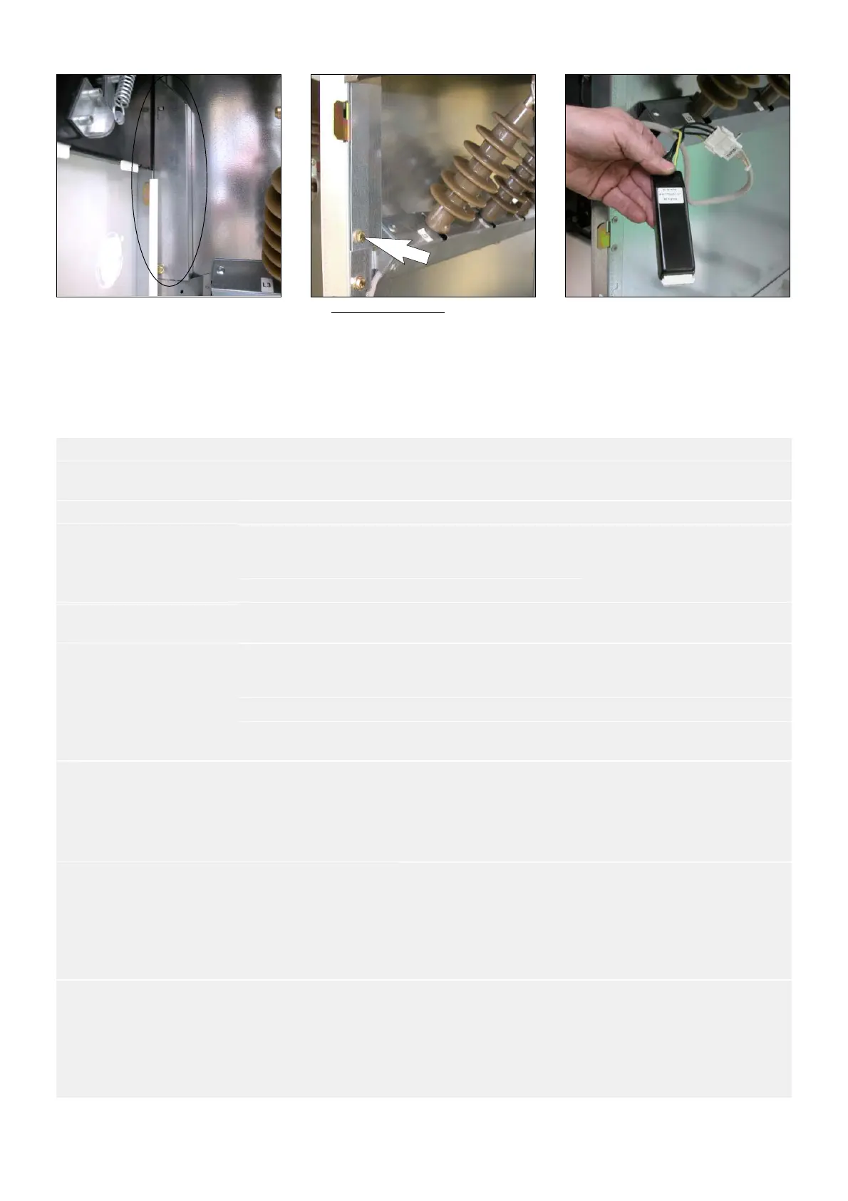
F Extract the VDS via the front,
disconnect it and replace it.
17.9 Possible anomalies and remedies
SYMPTOM DEVICE PROBABLE CAUSE REMEDY
Unusual noises
when energized, crackling,
Voltage presence box Plug badly connected to the
conductors
Check connections
vibrations
Capacitive insulator Accidental destruction Replace the voltage box
Insulators Insulating parts polluted or
degraded
Clean the insulating compo-
nents or call our After−Sales
Department (see § 1.1).
Cable ends Excessive humidity Install a heating element
Abnormal force required
when operating the
Control for the switch Safety interlocks Check the position of the brea-
king switchgear.
breaking switchgear
Earthing switch Safety interlocks Check the position of the brea-
king switchgear and the door
panel.
Voltage presence indicator
HV Fuses Fuse blown Replace the three fuses
extinguished with switch-
board energized)
Voltage indicator Deterioration of a compo-
nent
Replace the indicator(s)
Abnormal heating at
the connection points
Connections Badly tightened 1 − Clean the connecting plate
connections
2 − Replace the damaged
fasteners
3 − Retighten to appropriate
torque
Badly assembled 1 − Clean the connecting plate
connections
2 − Eliminate all material of a
different nature, placed in the
point of the current flow
3 − Retighten to appropriate
torque
Inappropriate tripping
operations inappropriate
Rings Badly connected 1 − Insulate the earthing screen
braids for the cables
2 − Pass these grounds into the
ring, in the reverse direction to
the cable, before connecting
them again to the switchboard’s
earthing point