20
6.10 Coupling of a Fluokit M24+ functional unit to a Fluokit M24 functional unit
The example given is for the coupl-
ing of a Fluokit M24+ functional unit
on the right of a Fluokit M24 func-
tional unit.
The coupling plate is different
according to whether the extension
is on the right or on the left.
F Remove the door of the Fluokit
M24+ functional unit to be
coupled.
F Mount the end plate if needed
(see § 6.1)
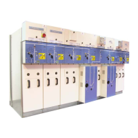
F Fastening points on the plate:
1 − 4 fastenings by M6 nuts
+ washers
2 − fastenings by H M8x20 bolts
3 − fastenings by M6 nuts
+ washers
1
2
3
3
3
2
Front
panel
Coupling
plate
F Press the plate against the
functional unit.
F Fasten the plate with 4 M6 nuts
+ washers [1] from the inside of
the functional unit
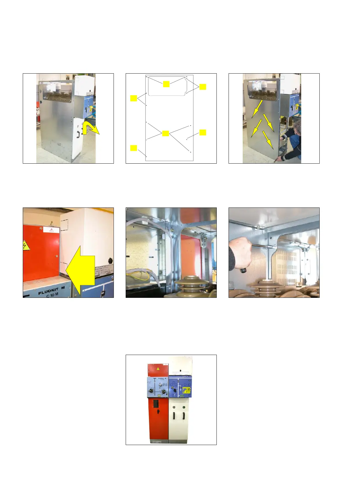
F Remove the end plate from the
M24 functional unit.
F Move the Fluokit M24+
functional unit close to the
switchboard.
F Fasten the coupling plate, on
the Fluokit M24 side, from the
inside of the functional unit [3].
F Remove the protective cover as
indicated in § 6.6.
F Fasten the functional units to
each other at the front [2].
F Fasten the functional units to
each other at the back [2].
F Complete coupling by mounting
the busbar and the earthing
circuit as indicated in § 6.4 &
6.6.