15
6 Installation
6.1 Installation of each Functional Unit
For all installation operations it is
advised that you use suitable pro-
tective gloves.
Organise the arrival of the Functio-
nal Units in accordance with the
single−line diagram.
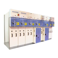
F To each far end Functional Unit
fix the blanking off side panel.
F Position the first Functional
Unit.
F Verify that it is upright.
F Mark out the coupling points:
− 7 distributed over the front
facing panel,
− 2 on the lower cross−bar,
− 2 on the upper cross−bar,
− 3 at the rear, in the cable
compartment.
F Place the second functional unit
alongside the first.
F Align the front panels.
F Interconnect the Functional
Units using all the fixing points
(H M8x20 bolts and nuts).
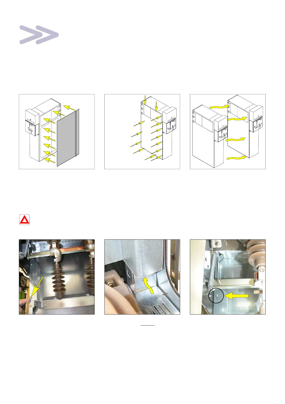
F Continuing with the assembly.
The coupling of the Functional
Units requires dismantling of
certain parts to be fitted back in
place again.
As an example, here is the wiring
cover placed in the upper left−hand
corner, at the front.
F Unscrew the fixing bolt on the
metal cover (10 mm spanner).
F Lift up then remove the cover.
F Carry out coupling.
F Replace the cover by inserting
its upper part behind the busbar
reinforcement.
F Engage the snug into the slot.
F Lower the cover.
F Screw in the fixing screw.
6.2 Functional units with internal arc withstand protection
Before setting in place, each func-
tional unit must be individually fitted
with its rear deflector (2 x HM6x16
screws).
During assembly, the deflectors
must also be interconnected
(HM8x16 bolt and nut).